TMP435
www.ti.com
SBOS495A –MARCH 2010–REVISED APRIL 2010
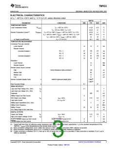
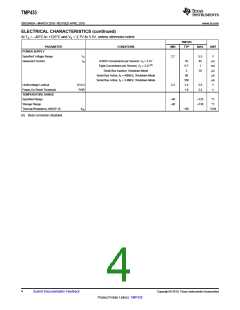
ELECTRICAL CHARACTERISTICS
At TA = –40°C to +125°C and VS = 2.7V to 5.5V, unless otherwise noted.
TMP435
PARAMETER
TEMPERATURE ERROR
CONDITIONS
MIN
TYP
MAX
UNIT
Local Temperature Sensor
TELOCAL
TA = –40°C to +125°C
TA = +0°C to +100°C, VS = 3.3V
±1.25
±0.25
±0.25
±0.5
±3
±2.5
±1
°C
°C
Remote Temperature Sensor(1)
TEREMOTE
TA = 0°C to +100°C, TDIODE = –40°C to +150°C, VS = 3.3V
TA = –40°C to +100°C, TDIODE = –40°C to +150°C, VS = 3.3V
TA = –40°C to +125°C, TDIODE = –40°C to +150°C
VS = 2.7V to 5.5V
±1
°C
±1.5
±5
°C
°C
vs Supply (Local/Remote)
TEMPERATURE MEASUREMENT
Conversion Time (per channel)
Local Channel
±0.2
±0.5
°C/V
12
15
17
ms
Remote Channel
(2)
RC = 1
RC = 0
RC = 1
RC = 0
97
36
72
33
126
47
137
52
ms
ms
ms
ms
MBeta Correction Enabled
(3)
93
100
47
MBeta Correction Disabled
44
Resolution
Local Channel
12
12
Bits
Bits
Remote Channel
Remote Sensor Source Currents
High
(4)
120
60
mA
mA
mA
mA
Series Resistance (beta correction)
Medium High
Medium Low
12
Low
6
Remote Transistor Ideality Factor
n
TMP435 optimized ideality factor
1.000(2)
1.008(3)
Beta Correction Range
b
0.1
2.1
27
SMBus INTERFACE
Logic Input High Voltage (SCL, SDA)
Logic Input Low Voltage (SCL, SDA)
Hysteresis
VIH
VIL
V
V
0.8
500
0.15
3
mV
mA
V
SMBus Output Low Sink Current
SDA Output Low Voltage
Logic Input Current
6
VOL
IOUT = 6mA
0.4
+1
0 ≤ VIN ≤ 6V
–1
mA
pF
MHz
ms
ms
SMBus Input Capacitance (SCL, SDA)
SMBus Clock Frequency
SMBus Timeout
3.4
35
1
25
32
SCL Falling Edge to SDA Valid Time
DIGITAL OUTPUTS
Output Low Voltage
VOL
IOH
IOUT = 6mA
VOUT = VS
0.15
0.1
0.4
1
V
High-Level Output Leakage Current
mA
mA
mA
ALERT/THERM2 Output Low Sink Current
THERM Output Low Sink Current
ALERT/THERM2 Forced to 0.4V
THERM2 Forced to 0.4V
6
6
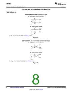
(1) Tested with less than 5Ω effective series resistance and 100pF differential input capacitance. TA is the ambient temperature of the
TMP435. TDIODE is the temperature at the remote diode sensor.
(2) Beta correction configuration set to '1000' and sensor is GND collector-connected (PNP collector to ground).
(3) Beta correction configuration set to '0111' or sensor is diode-connected (base shorted to collector).
(4) If beta correction is disabled ('0111'), then up to 1kΩ of series line resistance is cancelled; if beta correction is enabled ('1xxx'), up to
300Ω is cancelled.
Copyright © 2010, Texas Instruments Incorporated
Submit Documentation Feedback
3
Product Folder Link(s): TMP435

 TI [ TEXAS INSTRUMENTS ]