TMP435
www.ti.com
SBOS495A –MARCH 2010–REVISED APRIL 2010
TYPICAL CHARACTERISTICS (continued)
At TA = +25°C and VS = 3.3V, unless otherwise noted.
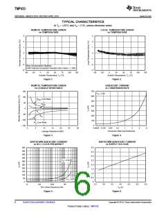
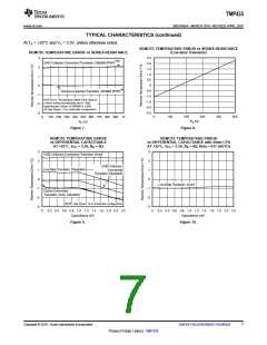
REMOTE TEMPERATURE ERROR vs SERIES RESISTANCE
(Low-Beta Transistor)
REMOTE TEMPERATURE ERROR vs SERIES RESISTANCE
2.5
3
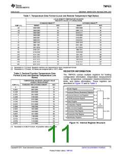
GND Collector-Connected Transistor, 2N3906 (PNP)(1)(2)
2.0
2
1.5
1.0
1
0
0.5
0
Diode-Connected Transistor, 2N3906 (PNP)(2)
-0.5
-1.0
-1.5
-2.0
-2.5
-1
NOTES (1): Temperature offset is the result of
n-factor being automatically set to 1.000.
-2
Approximate n-factor of 2N3906 is 1.008.
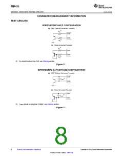
(2) See Figure 11 for schematic configuration.
-3
0
100
200
300
400
500
0
100 200 300 400 500 600 700 800 900 1k
RS (W)
RS (W)
Figure 7.
Figure 8.
REMOTE TEMPERATURE ERROR
vs DIFFERENTIAL CAPACITANCE
AT +25°C, VCC = 3.3V, RS = 0Ω
REMOTE TEMPERATURE ERROR
vs DIFFERENTIAL CAPACITANCE with 45nm CPU
AT +25°C, VCC = 3.3V, RS = 0Ω, Beta = 011 (AUTO)
3
2
3
2
1
0
GND Collector-Connected Transistor (Auto)
GND Collector-
Connected
Transistor (Disabled)
Low-Beta Transistor (Disabled)
1
0
Low-Beta Transistor (Auto)
-1
-2
-3
-1
Diode-Connected
Transistor (Auto, Disabled)
-2
-3
NOTE: See Figure 12 for schematic configuration.
0
0.2 0.4 0.6 0.8 1.0 1.2 1.4 1.6 1.8 2.0 2.2
Capacitance (nF)
0
0.2 0.4 0.6 0.8 1.0 1.2 1.4 1.6 1.8 2.0 2.2
Capacitance (nF)
Figure 9.
Figure 10.
Copyright © 2010, Texas Instruments Incorporated
Submit Documentation Feedback
7
Product Folder Link(s): TMP435

 TI [ TEXAS INSTRUMENTS ]