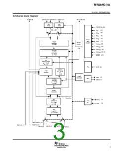
ꢀ ꢁꢂꢃ ꢄ ꢅ ꢆꢇ ꢈꢉꢉꢅ ꢃ
SLAS356 − DECEMBER 2001
†
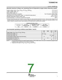
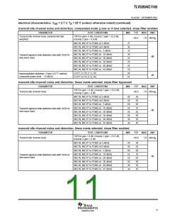
absolute maximum ratings over operating free-air temperature range (unless otherwise noted)
Supply voltage range, AV , DV , PLLV , EARV . . . . . . . . . . . . . . . . . . . . . . . . . . . . . . . . . . . . . . −0.5 V to 4 V
DD
DD
DD
DD
Output voltage range, V . . . . . . . . . . . . . . . . . . . . . . . . . . . . . . . . . . . . . . . . . . . . . . . . . . . . . . . . . . . . . . . . −0.5 V to 4 V
O
Input voltage range, V . . . . . . . . . . . . . . . . . . . . . . . . . . . . . . . . . . . . . . . . . . . . . . . . . . . . . . . . . . . . . . . . . . −0.5 V to 4 V
F
Continuous total power dissipation . . . . . . . . . . . . . . . . . . . . . . . . . . . . . . . . . . . . . . . . . . See Dissipation Rating Table
Operating free air temperature range, T (industrial temperature) . . . . . . . . . . . . . . . . . . . . . . . . . . . . . −40°C to 85°C
A
stg
Storage temperature range, testing, T
. . . . . . . . . . . . . . . . . . . . . . . . . . . . . . . . . . . . . . . . . . . . . . . . . −65°C to 150°C
Lead temperature 1,6 mm from case for 10 seconds . . . . . . . . . . . . . . . . . . . . . . . . . . . . . . . . . . . . . . . . . . . . . . . 260°C
Stresses beyond those listed under “absolute maximum ratings” may cause permanent damage to the device. These are stress ratings only, and
functional operation of the device at these or any other conditions beyond those indicated under “recommended operating conditions” is not
implied. Exposure to absolute-maximum-rated conditions for extended periods may affect device reliability.
†
DISSIPATION RATING TABLE
T
≤ 25°C
DERATING FACTOR
T = 85°C
A
POWER RATING
A
PACKAGE
POWER RATING
ABOVE T = 25°C
A
PBS
680 mW
6.8 mW/°C
270 mW
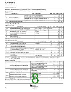
recommended operating conditions (see Notes 1 and 2)
MIN
NOM
MAX
UNIT
V
Supply voltage, AV , DV , PLLV , EARV
2.7
3.3
DD
DD
DD
DD
High-level input voltage, V
0.7 x V
V
IH
DD
Low-level input voltage, (V
IL
0.3 x V
32
V
DD
Load impedance between EAR1OP and EAR1ON-R
16
Ω
L
Load impedance for EAR2OP-R
32
Ω
L
Operating free-air temperature, T
−40
85
_C
A
NOTES: 1. To avoid possible damage and resulting reliability problems to these CMOS devices, the power-on initialization paragraph should
be followed, which is described in the Principles of Operations.
2. Voltages are with respect to AV , DV , PLLV , and EARV
.
SS SS SS SS
7
www.ti.com

 TI [ TEXAS INSTRUMENTS ]