ꢀ ꢁꢂ ꢃ ꢄꢅ ꢆꢇ ꢈ ꢉꢉ ꢅꢃ
SLAS356 − DECEMBER 2001
functional description
power on/reset
The power for the various digital and analog circuits is separated to improve the noise performance of the
device. An external reset must be applied to the active low RESET terminal to assure reset upon power on. After
the initial power-on sequence the TLV320AIC1103 can be functionally powered up and down by writing to the
2
power control register through the I C interface. There is a hardwired selectable power-up terminal in default
mode option. The PWRUPSEL function allows the VBAP to power up in the default mode and allows use without
a microcontroller.
reference
A precision band gap reference voltage is generated internally and supplies all required voltage references to
operate the transmit and receive channels. The reference system also supplies bias voltage for use with an
electret microphone at terminal MBIAS. An external precision resistor is required for reference current setting
at terminal REXT.
control interface
2
The I C interface is a two-wire bidirectional serial interface that controls the PCM codec by writing data to the
six control registers:
D
D
D
D
D
D
Power control
Mode control
Transmit PGA and sidetone control
Receive PGA gain and volume control
DTMF high tone
DTMF low tone
There are two power-up modes which may be selected at the PWRUPSEL terminal:
D
The PWRUPSEL state (V
at terminal 20) causes the device to power up in the default mode when power
DD
2
2
is applied. In the default mode, the I C interface is not required, and the device may be used without an I C
interface. The programmable functions are fixed in the default modes.
D
The PWRUPSEL state (ground at terminal 20) causes the device to go to a power-down state when power
is applied. In this mode an I C interface is required to power up the device.
2
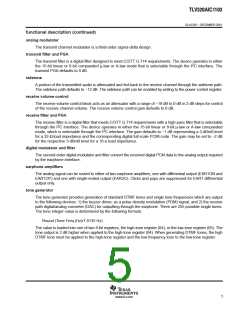
phase-locked loop
The internal digital filters and modulators require a 10.24-MHz clock that is generated by phase locking to the
2.048-MHz master clock input.
PCM interface
The PCM interface transmits and receives data at the PCMO and PCMI terminals respectively. The data is
transmitted or received at the PCMCLK speed once every PCMSYN cycle. The PCMCLK can be tied directly
to the 2.048-MHz master clock (MCLK). The PCMSYN can be driven by an external source or derived from the
master clock and used as an interrupt to the host controller.
microphone amplifiers
The microphone input is a switchable interface for two differential microphone inputs. The first stage is a low-
noise differential amplifier that provides a gain of 23.5 dB. The second stage amplifier has a selectable gain of
0 dB or 12 dB.
4
www.ti.com

 TI [ TEXAS INSTRUMENTS ]