ꢀ ꢁꢂꢃ ꢄ ꢅ ꢆꢇ ꢈꢉꢉꢅ ꢃ
SLAS356 − DECEMBER 2001
PRINCIPLES OF OPERATION
receive operation (continued)
Table 8. Receive-Data Bit Definitions
BIT NO.
COMPANDED
MODE
LINEAR
MODE
1
2
CD7
CD6
CD5
CD4
CD3
CD2
CD1
CD0
−
LD14
LD13
LD12
LD11
LD10
LD9
LD8
LD7
LD6
LD5
LD4
LD3
LD2
LD1
LD0
−−
3
4
5
6
7
8
9
10
11
12
13
14
15
16
−
−
−
−
−
−
−
Transmit channel gain control bits always follow the PCM data in time:
CD7−CD0 = data word in companded mode
LD14−LD0 = data word in linear mode
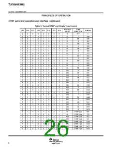
DTMF generator operation and interface
The dual-tone multifrequency generator (DTMF) circuit generates the summed DTMF tones for push button
dialing and provides the PDM output for the BUZZCON user-alert tone. There are 255 possible single tones.
The tone integer value is determined by the formula:
Round (tone frequency (Hz)/7.8125 Hz)
The integer value is loaded into either one of two 8-bit registers, high-tone register (04), or low-tone register (05).
The tone output is 2 dB higher when applied to the high-tone register (04). When generating DTMF tones, the
high frequency value must be applied to the high-tone register (04) and the low DTMF value to the low-tone
register.
25
www.ti.com

 TI [ TEXAS INSTRUMENTS ]