TLC7528C, TLC7528E, TLC7528I
DUAL 8-BIT MULTIPLYING
DIGITAL-TO-ANALOG CONVERTERS
SLAS062B – JANUARY 1987 – REVISED MARCH 2000
APPLICATION INFORMATION
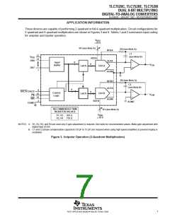
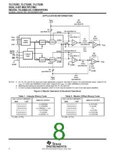
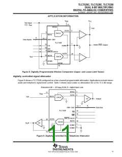
These devices are capable of performing 2-quadrant or full 4-quadrant multiplication. Circuit configurations for
2-quadrant and 4-quadrant multiplication are shown in Figures 3 and 4. Tables 1 and 2 summarize input coding
for unipolar and bipolar operation.
V
I(A)
±10 V
R1 (see Note A)
R2 (see Note A)
C1
RFBA
OUTA
AGND
17
14
(see Note B)
V
DD
REFA
DB0
–
+
8
Input
Buffer
8
V
OA
DACA
Latch
DB7
7
R4 (see Note A)
C2
RFBB
OUTB
(see Note B)
8
6
15
16
5
–
DACA/DACB
8
Control
Logic
DACB
Latch
V
OB
CS
+
WR
AGND
REFB
AGND
DGND
RECOMMENDED TRIM
RESISTOR VALUES
R3 (see Note A)
V
I(B)
±10 V
R1, R3 500 Ω
R2, R4 150 Ω
NOTES: A. R1, R2, R3, and R4 are used only if gain adjustment is required. See table for recommended values. Make gain adjustment with
digital input of 255.
B. C1 and C2 phase compensation capacitors (10 pF to 15 pF) are required when using high-speed amplifiers to prevent ringing or
oscillation.
Figure 3. Unipolar Operation (2-Quadrant Multiplication)
7
POST OFFICE BOX 655303 • DALLAS, TEXAS 75265

 TI [ TEXAS INSTRUMENTS ]