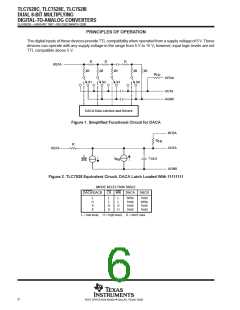
TLC7528C, TLC7528E, TLC7528I
DUAL 8-BIT MULTIPLYING
DIGITAL-TO-ANALOG CONVERTERS
SLAS062B – JANUARY 1987 – REVISED MARCH 2000
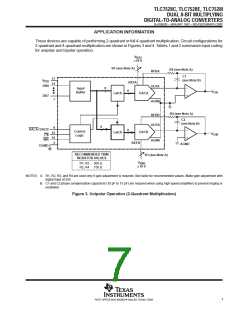
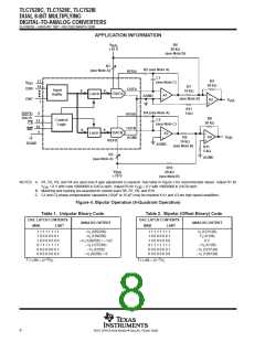
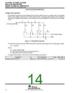
APPLICATION INFORMATION
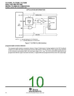
8
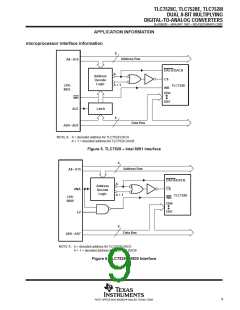
Address Bus
A8–A15
DACA/DACB
A
Address
Decode
Logic
IORQ
CS
TLC7528
WR
A + 1
CPU
Z80-A
DB0
DB7
WR
8
Data Bus
D0–D7
NOTE A: A = decoded address for TLC7528 DACA
A + 1 = decoded address for TLC7528 DACB
Figure 7. TLC7528 To Z-80A Interface
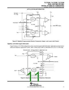
programmable window detector
The programmable window comparator shown in Figure 8 determines if voltage applied to the DAC feedback
resistors are within the limits programmed into the data latches of these devices. Input signal range depends
on the reference and polarity, that is, the test input range is 0 to –V . The DACA and DACB data latches are
ref
programmed with the upper and lower test limits. A signal within the programmed limits drives the output high.
10
POST OFFICE BOX 655303 • DALLAS, TEXAS 75265

 TI [ TEXAS INSTRUMENTS ]