TL284x, TL384x
CURRENT-MODE PWM CONTROLLERS
SLVS038E – JANUARY 1989 – REVISED DECEMBER 1999
electricalcharacteristics,V =15V(seeNote4),R =10kΩ,C =3.3nF,T =25°C(unlessotherwise
CC
T
T
A
specified) (continued)
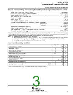
error-amplifier section
PARAMETER
TL384xY
TYP
2.50
–0.3
90
TEST CONDITIONS
COMP at 2.5 V
UNIT
MIN
MAX
Feedback input voltage
Input bias current
V
µA
dB
MHz
dB
mA
mA
V
Open-loop voltage amplification
Gain-bandwidth product
Supply-voltage rejection ratio
Output sink current
V
V
= 2 V to 4 V
O
1
= 12 V to 25 V
70
CC
VFB at 2.7 V,
VFB at 2.3 V,
VFB at 2.3 V,
VFB at 2.7 V,
COMP at 1.1 V
COMP at 5 V
6
Output source current
High-level output voltage
Low-level output voltage
–0.8
6
R
R
= 15 kΩ to GND
= 15 kΩ to GND
L
L
0.7
V
NOTE 4: Adjust V
above the start threshold before setting it to 15 V.
CC
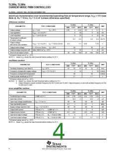
current-sense section
TL384xY
PARAMETER
TEST CONDITIONS
UNIT
MIN
TYP
3
MAX
Voltage amplification
See Notes 6 and 7
COMP at 5 V,
= 12 V to 25 V,
V/V
V
Current-sense comparator threshold
Supply-voltage rejection ratio
Input bias current
See Note 6
See Note 6
1
V
CC
70
–2
150
dB
µA
ns
Delay time to output
NOTES: 4. Adjust V
above the start threshold before setting it to 15 V.
CC
6. These parameters are measured at the trip point of the latch, with VFB at 0 V.
7. Voltage amplification is measured between ISENSE and COMP, with the input changing from 0 V to 0.8 V.
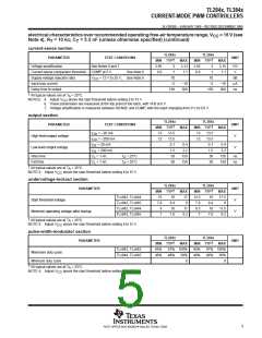
output section
TL384xY
TYP
13.5
13.5
0.1
PARAMETER
TEST CONDITIONS
= –20 mA
UNIT
V
MIN
MAX
I
I
I
I
OH
OH
OL
OL
High-level output voltage
Low-level output voltage
= –200 mA
= 20 mA
= 200 mA
= 1 nF
V
1.5
Rise time
Fall time
C
C
50
ns
ns
L
L
= 1 nF
50
NOTE 4: Adjust V
above the start threshold before setting it to 15 V.
CC
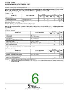
undervoltage-lockout section
TL384xY
TYP
16
PARAMETER
UNIT
V
MIN
MAX
TL3842Y, TL3844Y
TL3843Y, TL3845Y
TL3842Y, TL3844Y
TL3843Y, TL3845Y
Start threshold voltage
8.4
10
Minimum operating voltage after startup
V
7.6
NOTE 4: Adjust V
above the start threshold before setting it to 15 V.
CC
7
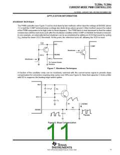
POST OFFICE BOX 655303 • DALLAS, TEXAS 75265

 TI [ TEXAS INSTRUMENTS ]