TL284x, TL384x
CURRENT-MODE PWM CONTROLLERS
SLVS038E – JANUARY 1989 – REVISED DECEMBER 1999
APPLICATION INFORMATION
2.5 V
0.5 mA
Error
Amplifier
+
–
VFB
Z
i
COMP
Z
f
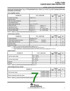
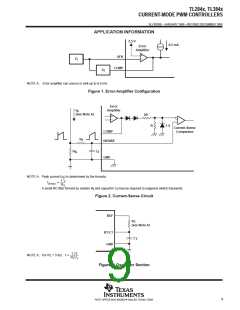
NOTE A: Error amplifier can source or sink up to 0.5 mA.
Figure 1. Error-Amplifier Configuration
Error
I
Amplifier
S
(see Note A)
2R
+
–
R
1 V
Current-Sense
Comparator
COMP
R
f
ISENSE
R
C
f
S
GND
NOTE A: Peak current (I ) is determined by the formula:
S
1 V
RS
IS max
(
)
A small RC filter formed by resistor R and capacitor C may be required to suppress switch transients.
f
f
Figure 2. Current-Sense Circuit
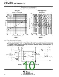
REF
R
T
(see Note A)
RT/CT
GND
C
T
1.72
RTCT
NOTE A: For R > 5 kΩ:
f
T
Figure 3. Oscillator Section
9
POST OFFICE BOX 655303 • DALLAS, TEXAS 75265

 TI [ TEXAS INSTRUMENTS ]