TL284x, TL384x
CURRENT-MODE PWM CONTROLLERS
SLVS038E – JANUARY 1989 – REVISED DECEMBER 1999
APPLICATION INFORMATION
shutdown technique
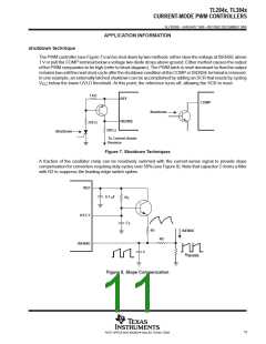
The PWM controller (see Figure 7) can be shut down by two methods: either raise the voltage at ISENSE above
1 V or pull the COMP terminal below a voltage two diode drops above ground. Either method causes the output
of the PWM comparator to be high (refer to block diagram). The PWM latch is reset dominant so that the output
remains low until the next clock cycle after the shutdown condition at the COMP or ISENSE terminal is removed.
In one example, an externally latched shutdown can be accomplished by adding an SCR that resets by cycling
V
below the lower UVLO threshold. At this point, the reference turns off, allowing the SCR to reset.
CC
1 kΩ
REF
COMP
Shutdown
ISENSE
330 Ω
500 Ω
Shutdown
To Current-Sense
Resistor
Figure 7. Shutdown Techniques
A fraction of the oscillator ramp can be resistively summed with the current-sense signal to provide slope
compensation for converters requiring duty cycles over 50% (see Figure 8). Note that capacitor C forms a filter
with R2 to suppress the leading-edge switch spikes.
REF
0.1 µF
R
T
RT/CT
C
T
R1
ISENSE
R2
ISENSE
C
R
SENSE
Figure 8. Slope Compensation
11
POST OFFICE BOX 655303 • DALLAS, TEXAS 75265

 TI [ TEXAS INSTRUMENTS ]