TCA9517
SCPS242 –DECEMBER 2012
www.ti.com
I2C INTERFACE TIMING REQUIREMENTS
VCCB = 2.7 V to 5.5 V, GND = 0 V, TA = –40°C to 85°C (unless otherwise noted)(1)(2)
FROM
(INPUT)
TO
(OUTPUT)
PARAMETER
TEST CONDITIONS
MIN TYP(3) MAX UNIT
SDAB, SCLB(4) SDAA, SCLA(4)
(see Figure 5) (see Figure 5)
SDAA, SCLA(5) SDAB, SCLB(5)
80
25
30
10
60
10
40
110
1
141 250
74 110
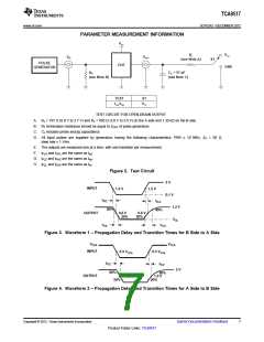
tPLZ
Propagation delay
ns
(see Figure 4)
(see Figure 4)
V
CCA ≤ 2.7 V
76(6) 110
(see Figure 3)
CCA ≥ 3 V
(see Figure 3)
SDAB, SCLB
SDAA, SCLA
V
tPZL
Propagation delay
86 230 ns
107 230
SDAA, SCLA(5) SDAB, SCLB(5)
(see Figure 4)
(see Figure 4)
VCCA ≤ 2.7 V
12
42
15
(see Figure 4)
B side to A side
VCCA ≥ 3 V
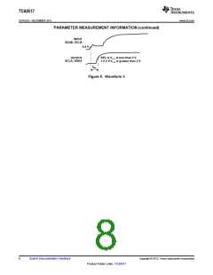
tTLH
Transition time
Transition time
80%
20%
45 ns
(see Figure 4)
A side to B side
(see Figure 3)
125 140
52(6) 105
67 175 ns
VCCA ≤ 2.7 V
(see Figure 4)
B side to A side
VCCA ≥ 3 V
tTHL
80%
20%
20
30
(see Figure 4)
A side to B side
(see Figure 3)
48
90
(1) Times are specified with loads of 1.35-kΩ pullup resistance and 50-pF load capacitance on the B side and 167-Ω pullup and 57-pF load
capacitance on the A side. Different load resistance and capacitance alter the RC time constant, thereby changing the propagation delay
and transition times.
(2) Pullup voltages are VCCA on the A side and VCCB on the B side.
(3) Typical values were measured with VCCA = VCCB = 3.3 V at TA = 25°C, unless otherwise noted.
(4) The tPLH delay data from B to A side is measured at 0.4 V on the B side to 0.5 VCCA on the A side when VCCA is less than 2 V, and
1.5 V on the A side if VCCA is greater than 2 V.
(5) The proportional delay data from A to B side is measured at 0.3 VCCA on the A side to 1.5 V on the B side.
(6) Typical value measured with VCCA = 2.7 V at TA = 25°C
6
Submit Documentation Feedback
Copyright © 2012, Texas Instruments Incorporated
Product Folder Links: TCA9517

 TI [ TEXAS INSTRUMENTS ]