TCA9517
www.ti.com
SCPS242 –DECEMBER 2012
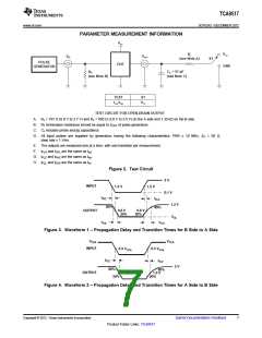
PARAMETER MEASUREMENT INFORMATION
VCC
VCC
RL
(see Note A)
VIN
VOUT
S1
PULSE
GENERATOR
DUT
GND
R
T
C = 57 pF
L
(see Note B)
(see Note C)
TEST
S1
tPLZ/tPZL
VCC
TEST CIRCUIT FOR OPEN-DRAIN OUTPUT
A. RL = 167 Ω (0.9 V to 2.7 V) and RL = 450 Ω (3.0 V to 5.5 V) on the A side and 1.35 kΩ on the B side
B. RT termination resistance should be equal to ZOUT of pulse generators.
C. CL includes probe and jig capacitance.
D. All input pulses are supplied by generators having the following characteristics: PRR ≤ 10 MHz, ZO = 50 Ω,
slew rate ≥ 1 V/ns.
E. The outputs are measured one at a time, with one transition per measurement.
F. tPLH and tPHL are the same as tpd
G. tPLZ and tPHZ are the same as tdis
H. tPZL and tPZH are the same as ten
.
.
.
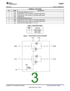
Figure 2. Test Circuit
3 V
INPUT
1.5 V
1.5 V
0.1 V
tPZL
80%
tPLZ
80%
1.2 V
OUTPUT
0.6 V
20%
0.6 V
20%
VOL
tTHL
tTLH
Figure 3. Waveform 1 – Propagation Delay and Transition Times for B Side to A Side
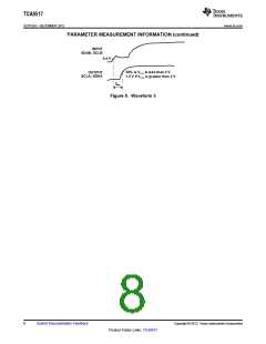
VCCA
VCCA
INPUT
0.3 VCCA
0.3 VCCA
tPZL
80%
20%
tPLZ
3 V
80%
1.5 V
OUTPUT
1.5 V
20%
Figure 4. Waveform 2 – Propagation Delay and Transition Times for A Side to B Side
Copyright © 2012, Texas Instruments Incorporated
Submit Documentation Feedback
7
Product Folder Links: TCA9517

 TI [ TEXAS INSTRUMENTS ]