TAS5711
www.ti.com
SLOS600 –DECEMBER 2009
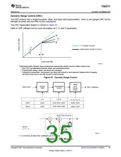
Dynamic Range Control (DRC)
The DRC scheme has a single threshold, offset, and slope (all programmable). There is one ganged DRC for the
left/right channels and one DRC for the subchannel.
The DRC input/output diagram is shown in Figure 52.
Refer to GDE software tool for more description on T, K, and O parameters.
K
1:1 Transfer Function
O
Implemented Transfer Function
T
Input Level (dB)
M0091-02
Professional-quality dynamic range compression automatically adjusts volume to flatten volume level.
• Each DRC has adjustable threshold, offset, and compression levels
• Programmable energy, attack, and decay time constants
• Transparent compression: compressors can attack fast enough to avoid apparent clipping before engaging,
and decay times can be set slow enough to avoid pumping.
Figure 52. Dynamic Range Control
Attack
and
Decay
Filters
Energy
Filter
Compression
Control
Audio Input
DRC Coefficient
a, w
T, K, O
aa, wa / ad, wd
0x3B / 0x3C
0x3E / 0x3F
DRC1
DRC2
0x3A
0x3D
0x40, 0x41, 0x42
0x43, 0x44, 0x45
Alpha Filter Structure
S
a
Z–1
w
NOTE:
w = 1 – α
B0265-01
T = 9.23 format, all other DRC coefficients are 3.23 format
Figure 53. DRC Structure
Copyright © 2009, Texas Instruments Incorporated
Submit Documentation Feedback
35
Product Folder Link(s): TAS5711

 TI [ TEXAS INSTRUMENTS ]