TAS5711
www.ti.com
SLOS600 –DECEMBER 2009
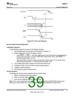
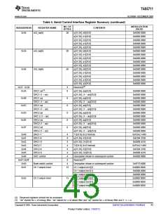
3 V
AVDD/DVDD
0 ns
2 ms
PDN
0 ns
2
I C
2 ms
RESET
2 ms
0 ns
8 V
PVDD
6 V
T0420-05
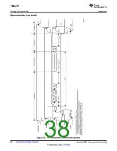
Figure 58. Power Loss Sequence
Recommended Command Sequences
Initialization Sequence
Use the following sequence to power-up and initialize the device:
1. Hold all digital inputs low and ramp up AVDD/DVDD to at least 3 V.
2. Initialize digital inputs and PVDD supply as follows:
•
Drive RESET = 0, PDN = 1, and other digital inputs to their desired state while ensuring that
all are never more than 2.5 V above AVDD/DVDD. Wait at least 100 µs, drive RESET = 1,
and wait at least another 13.5 ms.
•
Ramp up PVDD to at least 8 V while ensuring that it remains below 6 V for at least 100 µs
after AVDD/DVDD reaches 3 V. Then wait at least another 10 µs.
3. Trim oscillator (write 0x00 to register 0x1B) and wait at least 50 ms.
4. Configure the DAP via I2C (see Users's Guide for typical values).
5. Configure remaining registers.
6. Exit shutdown (sequence defined below).
Normal Operation
The following are the only events supported during normal operation:
1. Writes to master/channel volume registers.
2. Writes to soft mute register.
3. Enter and exit shutdown (sequence defined below).
Note: Event 3 is not supported for 240 ms + 1.3 × tstart after trim following AVDD/DVDD powerup ramp
(where tstart is 300 ms when mid-Z ramp is enabled and is otherwise specified by register 0x1A).
Copyright © 2009, Texas Instruments Incorporated
Submit Documentation Feedback
39
Product Folder Link(s): TAS5711

 TI [ TEXAS INSTRUMENTS ]