PGA281
www.ti.com
SBOS664A –MARCH 2013–REVISED JUNE 2013
ERROR INDICATORS
Error Flag Detection
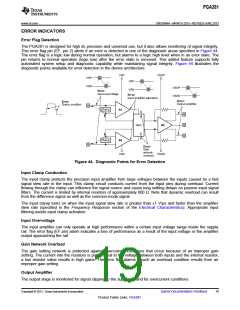
The PGA281 is designed for high dc precision and universal use, but it also allows monitoring of signal integrity.
This error flag pin (EF, pin 2) alerts if an error is detected in one of the diagnostic areas specified in Figure 44.
The error flag is a logic low during normal operation, but alarms to a logic high level when in an error state. The
pin returns to normal operation (logic low) after the error state is removed. This added feature supports fully
automated system setup and diagnostic capability while maintaining signal integrity. Figure 44 illustrates the
diagnostic points available for error detection in the device architecture.
VSOP
VSP
VSP
VSN
VSP
VSOP
VSON
VSN
Error:
Input overvoltage
Error:
Input amplifier saturation
Error:
Output amplifier
Error:
Clamp condition
Clamp
A1
Gain
A3
Clamp
A2
Error:
Gain
network
VSN
VSON
overload
Figure 44. Diagnostic Points for Error Detection
Input Clamp Conduction
The input clamp protects the precision input amplifier from large voltages between the inputs caused by a fast
signal slew rate in the input. This clamp circuit conducts current from the input pins during overload. Current
flowing through the clamp can influence the signal source and cause long settling delays on passive input signal
filters. The current is limited by internal resistors of approximately 600 Ω. Note that dynamic overload can result
from the difference signal as well as the common-mode signal.
The input clamp turns on when the input signal slew rate is greater than ±1 V/µs and faster than the amplifier
slew rate (specified in the Frequency Response section of the Electrical Characteristics). Appropriate input
filtering avoids input clamp activation.
Input Overvoltage
The input amplifier can only operate at high performance within a certain input voltage range inside the supply
rail. The error flag (EF pin) alarm indicates a loss of performance as a result of the input voltage or the amplifier
output approaching the rail.
Gain Network Overload
The gain setting network is protected against overcurrent conditions that occur because of an improper gain
setting. The current into the resistors is proportional to the voltage between both inputs and the internal resistor;
a low resistor value results in high gains. The error flag alarms if such an overload condition results from an
improper gain setting.
Output Amplifier
The output stage is monitored for signal clipping to the supply rail and for overcurrent conditions.
Copyright © 2013, Texas Instruments Incorporated
Submit Documentation Feedback
19
Product Folder Links: PGA281

 TI [ TEXAS INSTRUMENTS ]