PGA281
www.ti.com
SBOS664A –MARCH 2013–REVISED JUNE 2013
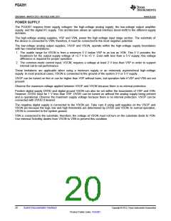
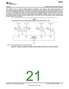
The PGA281 uses an internal chopper-stabilized architecture, and requires good supply decoupling. RC
decoupling using series resistors in the supply is recommended. Series resistors can be in the range of 15 Ω to
22 Ω. RC decoupling also prevents a very fast rise time of the supply voltage, thus avoiding parasitic currents in
the device. Connecting supply wires into an already turned-on supply (very fast rise time) without such a filter
can damage the device as a result of voltage overshoot and parasitic charge currents. Figure 45 shows an
example of a supply connection using RC bypass filters. DVDD may not need decoupling, but if the digital supply
is noisy, a filter is recommended.
NOTE
Rise and fall times for the high-voltage supplies must be slower than 1 V/μs.
5 V to 18 V
-5 V to -18 V
2.7 V to 5.5 V
2.7 V to 5.5 V
22 ꢀ
22 ꢀ
10 ꢀ
IQVSP
=
IQVSN
=
IQVSOP
=
IQVDD =
2.4 mA
(typ)
2.1 mA
(typ)
0.75 mA
(typ)
0.07 mA
(typ)
470 nF 470 nF
470 nF
100 nF
VSP
VSN
VSOP
DVDD
PGA281
Supply Connections
VSON
NOTE: The supply voltages shown are only example values.
Figure 45. Supply Connection Example Using RC Bypass Filters for Good Decoupling
Copyright © 2013, Texas Instruments Incorporated
Submit Documentation Feedback
21
Product Folder Links: PGA281

 TI [ TEXAS INSTRUMENTS ]