PGA281
SBOS664A –MARCH 2013–REVISED JUNE 2013
www.ti.com
Quiescent Current
The PGA281 uses internal resistor networks and switches to set the signal gain. Consequently, the current
through the resistor network may vary with the gain and signal amplitude. Under normal operation, the gain-
related current is low (less than 400 μA). However, in signal overload conditions while a high gain is selected,
this amount of current may increase.
Settling Time
The PGA281 provides very low drift and low noise, and therefore allows repeatable settling to a precise value.
Signal-related load and power-dissipation variables have minimal effect on device accuracy.
Overload Recovery
Overload conditions can vary widely and there are multiple points in an instrumentation amplifier that can be
overloaded. During input overload, the PGA281 folds the output signal partially back as a result of the differential
signal structure and summing, but the error flag indicates such fault conditions. The amplifier recovers safely
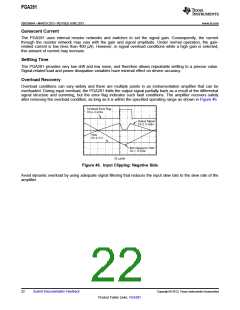
after removing the overload condition, as long as it is within the specified operating range as shown in Figure 46.
Overload Error Flag
Ch 4, 2-V/div
Output Signal
Ch 3, 2-V/div
VSN
Ch 2, 5-V
INN Clipped to VSN
Ch 1, 5-V/div
25 ms/div
Figure 46. Input Clipping: Negative Side
Avoid dynamic overload by using adequate signal filtering that reduces the input slew rate to the slew rate of the
amplifier.
22
Submit Documentation Feedback
Copyright © 2013, Texas Instruments Incorporated
Product Folder Links: PGA281

 TI [ TEXAS INSTRUMENTS ]