PCM9211
SBAS495 –JUNE 2010
www.ti.com
There are several allowable error sources from the DIR:
•
•
•
•
•
•
Change of incoming S/PDIF sample frequency (Register 25h / EFSCHG)
Out-of-range incoming S/PDIF signal (Register 25h / EFSLMT)
Non-PCM data (Register 25h / ENPCM)
Data invalid flag is the stream (Validity bit = '1') (Register 25h / EVALID)
Parity error (Register 25h / EPARITY)
PLL unlock (default) (Register 25h / EUNLOCK)
The error sources can be selected using Register 25h.
There are also several interrupts within the device that can be masked:
•
•
•
•
•
•
•
•
Error in DIR (this error is selectable from the list above in Register 25h)
When the device detects non-PCM data
When the Emphasis flag in the channel status of the incoming data has been set
When DTS-CD data have been detected by the device
When the Channel Status (CS) is updated
When Burst Preamble (PC) is updated
When the sampling frequency is changed.
When the analog input crosses the Analog Input Detect level (available only on INT1).
Each interrupt source can be masked by Register 2Ah (INT0) and Register 2Bh (INT1).
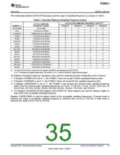
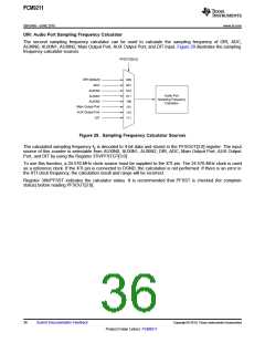
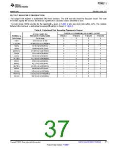
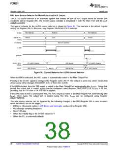
DIR: Sampling Frequency Calculator for Incoming S/PDIF Inputs
The PCM9211 has two integrated sampling frequency calculators. The first calculator is always connected to the
output of the DIR. It calculates the actual sampling frequency of the incoming S/PDIF signal. The result can be
read from a register, or output through the MPIO pins. Note that this process is not the same as reading the
Channel Status value for the sample rate that the transmitting equipment may be sending.
To use this function, a 24.576-MHz clock source must be supplied to the XTI pin. The 24.576-MHz clock is used
as a reference clock to calculate the incoming S/PDIF sampling frequency. If the XTI pin is connected to DGND,
the function is disabled and the calculation is not performed. If there is an error in the XTI clock frequency, the
calculation result and range will be incorrect.
The result is decoded into 4-bit data and stored in Register 39h/SFSOUT[3:0]; the MPIO pins are then assigned
to the SFSOUT[3:0] function.
The data in the SFSOUT[3:0] register (and available as a signal for the MPIO section) are the calculated
sampling frequency based on the incoming S/PDIF stream, and not what is reported in Channel Status bits 24 to
27. If the PLL becomes unlocked, or attempts to run out of range, SFSOUT[3:0] = '0000' is output, and indicates
abnormal operation.
If the XTI source clock is not supplied before the PCM9211 powers up, SFSOUT [3:0] outputs '0000'. If the XTI
source clock is stopped, the fS calculator holds its most recent calculated result. Once the XTI source clock is
restored, the fS calculator resumes operation.
Register 39h/SFSST indicates the calculator status. Before reading SFSOUT[3:0], it is recommended that the
user verify that the SFSST status is '0'.
34
Submit Documentation Feedback
Copyright © 2010, Texas Instruments Incorporated
Product Folder Link(s): PCM9211

 TI [ TEXAS INSTRUMENTS ]