PCM9211
SBAS495 –JUNE 2010
www.ti.com
DIR: Parity Error Processing
Error detection and processing for parity errors behave in the following manner:
•
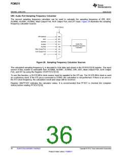
For PCM data, when an error is detected (for example, a parity error), then the data from the previous sample
are repeated. This sequence is shown in Figure 26, where sample Ln+1 is repeated because the incoming
data (Ln+2) had an error.
•
For non-PCM data, the data are output as is with no changes. (Non-PCM data implies data which has
Channel Status bit 1 = '1'.)
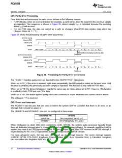
Figure 26 shows the processing for parity error occurrence.
[FOR PCM SIGNAL]
Internal LOCK
LRCKO (I2S)
ERROR
DOUT
MUTE (Low)
L
n
Rn
L
n+1
Rn+1
Ln+1
Rn+2
L
n+3
Rn+3
Interpolation processing by previous data
Parity error
[FOR NON-PCM SIGNAL ]
Internal LOCK
LRCKO (I2S)
ERROR
DOUT
MUTE (Low)
L
n
Rn
L
n+1
Rn+1
Ln+2
Rn+2
L
n+3
Rn+3
Parity error
Figure 26. Processing for Parity Error Occurrence
The PCM9211 handles parity errors as directed by the 23h/PRTPRO[1:0] registers.
When set to '01', if the error is received eight times sequentially, the DIR output is muted on the next error. Until
the mute is enabled, the previously accurate sample is repeated. This function is only valid for PCM data.
When set to '10', the device behaves in exactly the same way as it does when set to '01'. However, this function
is enabled for both PCM and non-PCM data.
When set to '00', the device ignores parity errors and continues to output whatever data comes into the device.
The setting on '11' is reserved.
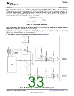
DIR: Errors and Interrupts
The PCM9211 has two pins that are used to inform the system DSP or controller that there is an error, or an
interrupt that it should be aware of.
The ERR/INT0 and NPCM/INT1 pins can be configured in these ways:
HARDWARE PIN
ERR/INTO0
OPTIONS
DIR Error (default), INT0 or Hi-Z
DIR NPCM (default), INT1 or Hi-Z
NPCM/INT1
When configured as direct DIR error connections (ERR, NPCM), the system audio processor typically treats
them as dedicated interrupt pins to change or control audio processing software. An example would be that the
system may mute if an ERR signal is detected. Another example is that if the DSP receives an NPCM interrupt, it
begins looking for AC-3 or DTS preambles in the incoming encoded S/PDIF stream.
For more advanced users, the two pins can be set up as interrupt sources. The seven interrupt sources
(ERROR, NPCM, DTS-CD/LD, Emphasis, Channel Status Start, Burst Preamble Start, fS Calculator Complete)
can be masked into Registers INT0 and INT1.
32
Submit Documentation Feedback
Copyright © 2010, Texas Instruments Incorporated
Product Folder Link(s): PCM9211

 TI [ TEXAS INSTRUMENTS ]