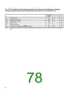
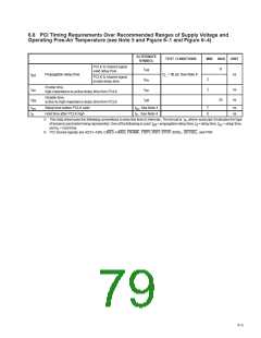
6.5 PCI Clock/Reset Timing Requirements Over Recommended Ranges of Supply
Voltage and Operating Free-Air Temperature (see Figure 6–2 and Figure 6–3)
ALTERNATE
SYMBOL
MIN
MAX
UNIT
t
t
t
Cycle time, PCLK
t
30
11
11
1
∞
ns
ns
c
cyc
Pulse duration, PCLK high
Pulse duration, PCLK low
Slew rate, PCLK
t
high
wH
wL
t
ns
low
t , t
∆v/∆t
4
V/ns
ms
ms
r f
t
t
Pulse duration, RSTIN
t
1
w
rst
Setup time, PCLK active at end of RSTIN (see Note 4 )
t
100
su
rst-clk
NOTE 4: The setup and hold times for the secondary are identical to those for the primary; however, the times are relative to the secondary PCI
close.
6–4

 TI [ TEXAS INSTRUMENTS ]