OMAP-L137 Low-Power Applications Processor
SPRS563A–SEPTEMBER 2008–REVISED OCTOBER 2008
www.ti.com
6.25 Universal Asynchronous Receiver/Transmitter (UART)
OMAP-L137 has 3 UART peripherals. Each UART has the following features:
•
•
•
•
•
•
•
•
•
16-byte storage space for both the transmitter and receiver FIFOs
1, 4, 8, or 14 byte selectable receiver FIFO trigger level for autoflow control and DMA
DMA signaling capability for both received and transmitted data
Programmable auto-rts and auto-cts for autoflow control
Programmable Baud Rate up to 3MBaud
Programmable Oversampling Options of x13 and x16
Frequency pre-scale values from 1 to 65,535 to generate appropriate baud rates
Prioritized interrupts
Programmable serial data formats
–
–
–
5, 6, 7, or 8-bit characters
Even, odd, or no parity bit generation and detection
1, 1.5, or 2 stop bit generation
•
•
•
False start bit detection
Line break generation and detection
Internal diagnostic capabilities
–
–
Loopback controls for communications link fault isolation
Break, parity, overrun, and framing error simulation
•
Modem control functions (CTS, RTS) on UART0 only.
The UART registers are listed in Section 6.25.1
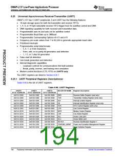
6.25.1 UART Peripheral Registers Description(s)
Table 6-86 is the list of UART registers.
Table 6-86. UART Registers
UART0
UART1
UART2
REGISTER NAME Register Description
BYTE ADDRESS
BYTE ADDRESS
BYTE ADDRESS
0x01D0 D000
0x01D0 D000
0x01D0 D004
0x01D0 D008
0x01D0 D008
0x01D0 D00C
0x01D0 D010
0x01D0 D014
0x01D0 D020
0x01D0 D024
0x01D0 D028
0x01D0 D030
0x01D0 D034
0x01C4 2000
0x01C4 2000
0x01C4 2004
0x01C4 2008
0x01C4 2008
0x01C4 200C
0x01C4 2010
0x01C4 2014
0x01C4 2020
0x01C4 2024
0x01C4 2028
0x01C4 2030
0x01C4 2034
0x01D0 C000
0x01D0 C000
0x01D0 C004
0x01D0 C008
0x01D0 C008
0x01D0 C00C
0x01D0 C010
0x01D0 C014
0x01D0 C020
0x01D0 C024
0x01D0 C028
0x01D0 C030
0x01D0 C034
RBR
THR
IER
Receiver Buffer Register (read only)
Transmitter Holding Register (write only)
Interrupt Enable Register
IIR
Interrupt Identification Register (read only)
FIFO Control Register (write only)
Line Control Register
FCR
LCR
MCR
LSR
DLL
Modem Control Register
Line Status Register
Divisor LSB Latch
DLH
REVID1
Divisor MSB Latch
Revision Identification Register 1
PWREMU_MGMT Power and Emulation Management Register
MDR Mode Definition Register
194
Peripheral Information and Electrical Specifications
Submit Documentation Feedback

 TI [ TEXAS INSTRUMENTS ]