OMAP-L137 Low-Power Applications Processor
SPRS563A–SEPTEMBER 2008–REVISED OCTOBER 2008
www.ti.com
6.24 Inter-Integrated Circuit Serial Ports (I2C0, I2C1)
6.24.1 I2C Device-Specific Information
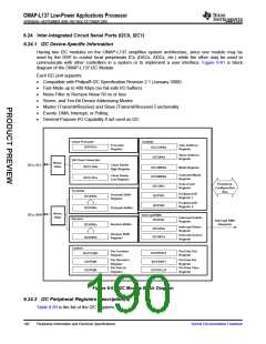
Having two I2C modules on the OMAP-L137 simplifies system architecture, since one module may be
used by the DSP to control local peripherals ICs (DACs, ADCs, etc.) while the other may be used to
communicate with other controllers in a system or to implement a user interface. Figure 6-61 is block
diagram of the OMAP-L137 I2C Module.
Each I2C port supports:
•
•
•
•
•
•
•
Compatible with Philips® I2C Specification Revision 2.1 (January 2000)
Fast Mode up to 400 Kbps (no fail-safe I/O buffers)
Noise Filter to Remove Noise 50 ns or less
Seven- and Ten-Bit Device Addressing Modes
Master (Transmit/Receive) and Slave (Transmit/Receive) Functionality
Events: DMA, Interrupt, or Polling
General-Purpose I/O Capability if not used as I2C
Clock Prescaler
I2CPSCx
Control
I2CCOARx
Prescaler
Register
Own Address
Register
Slave Address
Register
I2CSARx
Bit Clock Generator
I2CCLKHx
Noise
Filter
I2Cx_SCL
Clock Divide
High Register
I2CCMDRx
I2CEMDRx
I2CCNTx
I2CPID1
Mode Register
Extended Mode
Register
Clock Divide
Low Register
I2CCLKLx
Data Count
Register
Peripheral
Configuration
Bus
Transmit
I2CXSRx
Peripheral ID
Register 1
Transmit Shift
Register
Peripheral ID
Register 2
I2CPID2
I2CDXRx
Transmit Buffer
Noise
Filter
I2Cx_SDA
Interrupt/DMA
Interrupt Enable
Register
Receive
I2CIERx
Interrupt DMA
Requests
Receive Buffer
I2CDRRx
Interrupt Status
Register
I2CSTRx
I2CSRCx
Receive Shift
Register
Interrupt Source
Register
I2CRSRx
Control
Pin Function
Register
Pin Data Out
Register
I2CPDOUT
I2CPFUNC
Pin Direction
Register
Pin Data In
Register
Pin Data Set
Register
Pin Data Clear
Register
I2CPDIR
I2CPDIN
I2CPDSET
I2CPDCLR
Figure 6-61. I2C Module Block Diagram
6.24.2 I2C Peripheral Registers Description(s)
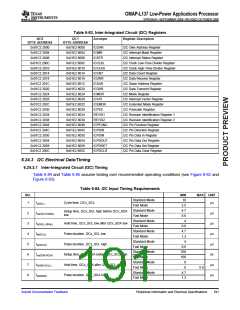
Table 6-83 is the list of the I2C registers.
190
Peripheral Information and Electrical Specifications
Submit Documentation Feedback

 TI [ TEXAS INSTRUMENTS ]