OMAP-L137 Low-Power Applications Processor
SPRS563A–SEPTEMBER 2008–REVISED OCTOBER 2008
www.ti.com
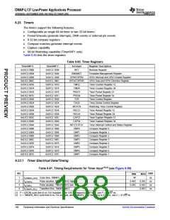
6.23 Timers
The timers support the following features:
•
•
•
•
•
•
Configurable as single 64-bit timer or two 32-bit timers
Period timeouts generate interrupts, DMA events or external pin events
8 32-bit compare registers
Compare matches generate interrupt events
Capture capability
64-bit Watchdog capability (Timer64P1 only)
Table 6-80 lists the timer registers.
Table 6-80. Timer Registers
Timer64P 0
0x01C2 0000
0x01C2 0004
0x01C2 0008
0x01C2 000C
0x01C2 0010
0x01C2 0014
0x01C2 0018
0x01C2 001C
0x01C2 0020
0x01C2 0024
0x01C2 0028
0x01C2 0034
0x01C2 0038
0x01C2 003C
0x01C2 0040
0x01C2 0044
0x01C2 0060
0x01C2 0064
0x01C2 0068
0x01C2 006C
0x01C2 0070
0x01C2 0074
0x01C2 0078
0x01C2 007C
Timer64P 1
0x01C2 1000
0x01C2 1004
0x01C2 1008
0x01C2 100C
0x01C2 1010
0x01C2 1014
0x01C2 1018
0x01C2 101C
0x01C2 1020
0x01C2 1024
0x01C2 1028
0x01C2 1034
0x01C2 1038
0x01C2 103C
0x01C2 1040
0x01C2 1044
0x01C2 1060
0x01C2 1064
0x01C2 1068
0x01C2 106C
0x01C2 1070
0x01C2 1074
0x01C2 1078
0x01C2 107C
Acronym
REV
Register Description
Revision Register
EMUMGT
GPINTGPEN
GPDATGPDIR
TIM12
Emulation Management Register
GPIO Interrupt and GPIO Enable Register
GPIO Data and GPIO Direction Register
Timer Counter Register 12
Timer Counter Register 34
Timer Period Register 12
Timer Period Register 34
Timer Control Register
TIM34
PRD12
PRD34
TCR
TGCR
Timer Global Control Register
Watchdog Timer Control Register
Timer Reload Register 12
Timer Reload Register 34
Timer Capture Register 12
Timer Capture Register 34
Timer Interrupt Control and Status Register
Compare Register 0
WDTCR
REL12
REL34
CAP12
CAP34
INTCTLSTAT
CMP0
CMP1
Compare Register 1
CMP2
Compare Register 2
CMP3
Compare Register 3
CMP4
Compare Register 4
CMP5
Compare Register 5
CMP6
Compare Register 6
CMP7
Compare Register 7
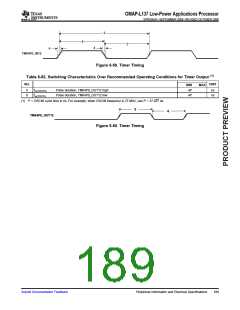
6.23.1 Timer Electrical Data/Timing
Table 6-81. Timing Requirements for Timer Input(1)(2) (see Figure 6-59)
NO.
UNIT
MIN
4P
MAX
1
2
3
4
tc(TM64Px_IN12) Cycle time, TM64Px_IN12
ns
ns
ns
ns
tw(TINPH)
tw(TINPL)
Pulse duration, TM64Px_IN12 high
Pulse duration, TM64Px_IN12 low
0.45C
0.45C
0.55C
0.55C
0.05C
tt(TM64Px_IN12) Transition time, TM64Px_IN12
(1) P = OSCIN cycle time in ns. For example, when OSCIN frequency is 27 MHz, use P = 37.037 ns.
(2) C = TM64P0_IN12 cycle time in ns. For example, when TM64Px_IN12 frequency is 27 MHz, use C = 37.037 ns
188
Peripheral Information and Electrical Specifications
Submit Documentation Feedback

 TI [ TEXAS INSTRUMENTS ]