OMAP-L137 Low-Power Applications Processor
SPRS563A–SEPTEMBER 2008–REVISED OCTOBER 2008
www.ti.com
6.10.5 EMIFA Electrical Data/Timing
Table 6-18 through Table 6-21 assume testing over recommended operating conditions.
Table 6-18. EMIFA SDRAM Interface Timing Requirements
NO.
MIN
MAX UNIT
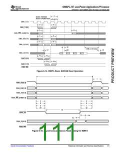
Input setup time, read data valid on EMA_D[31:0] before EMA_CLK
rising
19
tsu(EMA_DV-EM_CLKH)
th(CLKH-DIV)
1
ns
Input hold time, read data valid on EMA_D[31:0] after EMA_CLK
rising
20
1.5
ns
Table 6-19. EMIFA SDRAM Interface Switching Characteristics
NO.
1
PARAMETER
MIN
10
3
MAX UNIT
tc(CLK)
Cycle time, EMIF clock EMA_CLK
ns
ns
2
tw(CLK)
Pulse width, EMIF clock EMA_CLK high or low
Delay time, EMA_CLK rising to EMA_CS[0] valid
Output hold time, EMA_CLK rising to EMA_CS[0] invalid
Delay time, EMA_CLK rising to EMA_WE_DQM[1:0] valid
Output hold time, EMA_CLK rising to EMA_WE_DQM[1:0] invalid
3
td(CLKH-CSV)
toh(CLKH-CSIV)
td(CLKH-DQMV)
toh(CLKH-DQMIV)
7
7
ns
ns
ns
ns
4
1
1
5
6
Delay time, EMA_CLK rising to EMA_A[12:0] and EMA_BA[1:0]
valid
7
8
td(CLKH-AV)
7
ns
ns
Output hold time, EMA_CLK rising to EMA_A[12:0] and
EMA_BA[1:0] invalid
toh(CLKH-AIV)
1
9
td(CLKH-DV)
Delay time, EMA_CLK rising to EMA_D[15:0] valid
Output hold time, EMA_CLK rising to EMA_D[15:0] invalid
Delay time, EMA_CLK rising to EMA_RAS valid
7
7
7
7
7
ns
ns
ns
ns
ns
ns
ns
ns
ns
ns
10
11
12
13
14
15
16
17
18
toh(CLKH-DIV)
td(CLKH-RASV)
toh(CLKH-RASIV)
td(CLKH-CASV)
toh(CLKH-CASIV)
td(CLKH-WEV)
toh(CLKH-WEIV)
tdis(CLKH-DHZ)
tena(CLKH-DLZ)
1
1
1
1
1
Output hold time, EMA_CLK rising to EMA_RAS invalid
Delay time, EMA_CLK rising to EMA_CAS valid
Output hold time, EMA_CLK rising to EMA_CAS invalid
Delay time, EMA_CLK rising to EMA_WE valid
Output hold time, EMA_CLK rising to EMA_WE invalid
Delay time, EMA_CLK rising to EMA_D[15:0] tri-stated
Output hold time, EMA_CLK rising to EMA_D[15:0] driving
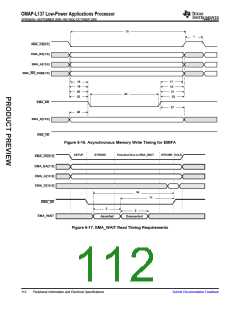
Table 6-20. EMIFA Asynchronous Memory Timing Requirements(1)
OMAP-L137
NO
.
UNIT
MIN
Nom
MAX
READS and WRITES
Pulse duration, EM_WAIT assertion and
deassertion
2
tw(EM_WAIT)
2E
ns
READS
12 tsu(EMDV-EMOEH) Setup time, EM_D[15:0] valid before EM_OE high
3
ns
ns
13 th(EMOEH-EMDIV)
Hold time, EM_D[15:0] valid after EM_OE high
0.5
tsu(EMOEL-
EMWAIT)
Setup Time, EM_WAIT asserted before end of
Strobe Phase(2)
14
4E+3
ns
WRITES
(1) E = EMA_CLK period or in ns. EMA_CLK is selected either as SYSCLK3 or the PLL output clock divided by 4.5. As an example, when
SYSCLK3 is selected and set to 100MHz, E=10ns.
(2) Setup before end of STROBE phase (if no extended wait states are inserted) by which EM_WAIT must be asserted to add extended
wait states. Figure 6-17 and Figure 6-18 describe EMIF transactions that include extended wait states inserted during the STROBE
phase. However, cycles inserted as part of this extended wait period should not be counted; the 4E requirement is to the start of where
the HOLD phase would begin if there were no extended wait cycles.
108
Peripheral Information and Electrical Specifications
Submit Documentation Feedback

 TI [ TEXAS INSTRUMENTS ]