OMAP-L137 Low-Power Applications Processor
www.ti.com
SPRS563A–SEPTEMBER 2008–REVISED OCTOBER 2008
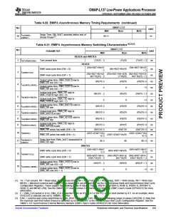
Table 6-20. EMIFA Asynchronous Memory Timing Requirements (continued)
OMAP-L137
Nom
NO
.
UNIT
MIN
MAX
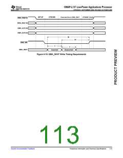
tsu(EMWEL-
EMWAIT)
Setup Time, EM_WAIT asserted before end of
Strobe Phase(2)
28
4E+3
ns
Table 6-21. EMIFA Asynchronous Memory Switching Characteristics(1)(2)(3)
OMAP-L137
NO
.
PARAMETER
UNIT
MIN
Nom
MAX
READS and WRITES
(TA)*E - 3
1
3
td(TURNAROUND)
Turn around time
(TA)*E
(TA)*E + 3
ns
READS
(RS+RST+RH)*E
- 3
(RS+RST+RH)*E
+ 3
EMIF read cycle time (EW = 0)
EMIF read cycle time (EW = 1)
(RS+RST+RH)*E
ns
ns
ns
ns
ns
ns
ns
ns
ns
tc(EMRCYCLE)
(RS+RST+RH+(E (RS+RST+RH+(EW (RS+RST+RH+(E
WC*16))*E - 3
C*16))*E
WC*16))*E + 3
Output setup time, EMA_CE[5:2] low to
EMA_OE low (SS = 0)
(RS)*E-3
(RS)*E
(RS)*E+3
4
5
tsu(EMCEL-EMOEL)
Output setup time, EMA_CE[5:2] low to
EMA_OE low (SS = 1)
-3
(RH)*E - 3
-3
0
(RH)*E
0
+3
(RH)*E + 3
+3
Output hold time, EMA_OE high to
EMA_CE[5:2] high (SS = 0)
th(EMOEH-EMCEH)
Output hold time, EMA_OE high to
EMA_CE[5:2] high (SS = 1)
Output setup time, EMA_BA[1:0] valid to
EMA_OE low
6
7
8
9
tsu(EMBAV-EMOEL)
th(EMOEH-EMBAIV)
tsu(EMBAV-EMOEL)
th(EMOEH-EMAIV)
(RS)*E-3
(RH)*E-3
(RS)*E-3
(RS)*E
(RH)*E
(RS)*E
(RS)*E+3
(RH)*E+3
(RS)*E+3
Output hold time, EMA_OE high to
EMA_BA[1:0] invalid
Output setup time, EMA_A[13:0] valid to
EMA_OE low
Output hold time, EMA_OE high to
EMA_A[13:0] invalid
(RH)*E-3
(RH)*E
(RST)*E
(RH)*E+3
ns
ns
ns
EMA_OE active low width (EW = 0)
(RST)*E-3
(RST)*E+3
10 tw(EMOEL)
(RST+(EWC*16))
*E-3
(RST+(EWC*16))
*E+3
EMA_OE active low width (EW = 1)
(RST+(EWC*16))*E
td(EMWAITH-
EMOEH)
Delay time from EMA_WAIT deasserted to
EMA_OE high
11
3E-3
4E
4E+3
ns
WRITES
(WS+WST+WH)*
E-3
(WS+WST+WH)*
E+3
EMIF write cycle time (EW = 0)
EMIF write cycle time (EW = 1)
(WS+WST+WH)*E
ns
ns
ns
ns
15 tc(EMWCYCLE)
(WS+WST+WH+( (WS+WST+WH+(E (WS+WST+WH+(
EWC*16))*E - 3
WC*16))*E
EWC*16))*E + 3
Output setup time, EMA_CE[5:2] low to
EMA_WE low (SS = 0)
(WS)*E - 3
(WS)*E
(WS)*E + 3
16 tsu(EMCEL-EMWEL)
Output setup time, EMA_CE[5:2] low to
EMA_WE low (SS = 1)
-3
0
+3
(1) TA = Turn around, RS = Read setup, RST = Read strobe, RH = Read hold, WS = Write setup, WST = Write strobe, WH = Write hold,
MEWC = Maximum external wait cycles. These parameters are programmed via the Asynchronous Bank and Asynchronous Wait Cycle
Configuration Registers. These support the following range of values: TA[4-1], RS[16-1], RST[64-1], RH[8-1], WS[16-1], WST[64-1],
WH[8-1], and MEW[1-256]. See the OMAP-L137 Asynchronous External Memory Interface (EMIF) User's Guide (SPRUED1) for more
information.
(2) E = EMA_CLK period or in ns. EMA_CLK is selected either as SYSCLK3 or the PLL output clock divided by 4.5. As an example, when
SYSCLK3 is selected and set to 100MHz, E=10ns.
(3) EWC = external wait cycles determined by EMA_WAIT input signal. EWC supports the following range of values EWC[256-1]. Note that
the maximum wait time before timeout is specified by bit field MEWC in the Asynchronous Wait Cycle Configuration Register. See the
OMAP-L137 Asynchronous External Memory Interface (EMIF) User's Guide (SPRUED1) for more information.
Submit Documentation Feedback
Peripheral Information and Electrical Specifications
109

 TI [ TEXAS INSTRUMENTS ]