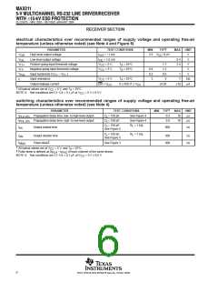
ꢀ ꢁ ꢂ ꢃꢄꢄ
ꢅꢆ ꢇ ꢀ ꢈꢉꢊ ꢋ ꢌ ꢍꢁ ꢎ ꢎꢏꢉ ꢐꢑ ꢆꢃ ꢒ ꢃ ꢉꢋ ꢎ ꢏ ꢓꢐ ꢋ ꢇꢏ ꢐꢔꢐꢏ ꢌꢏꢋ ꢇꢏꢐ
ꢕꢋ ꢊ ꢍ ꢄ ꢅꢆ ꢖꢇ ꢏꢑ ꢓ ꢗ ꢐꢘ ꢊꢏ ꢌꢊꢋ ꢘ ꢎ
SLLS567E − MAY 2003 − REVISED JANUARY 2004
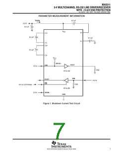
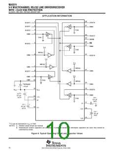
PARAMETER MEASUREMENT INFORMATION
0 V
SHDN
3 V
0 V
Input
1.5 V
1.5 V
RS-232
Output
Generator
(see Note B)
50 Ω
t
t
PLH (D)
C
PHL (D)
L
R
(see Note A)
L
V
OH
OL
3 V
−3 V
3 V
−3 V
Output
V
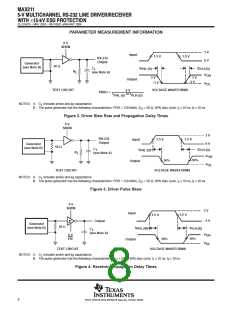
TEST CIRCUIT
VOLTAGE WAVEFORMS
6 V
or t
SR(tr) +
t
PHL (D)
PLH (D)
NOTES: A.
C includes probe and jig capacitance.
L
B. The pulse generator has the following characteristics: PRR = 120 kbit/s, Z = 50 Ω, 50% duty cycle, t ≤ 10 ns, t ≤ 10 ns.
O
r
f
Figure 2. Driver Slew Rate and Propagation Delay Times
0 V
SHDN
3 V
RS-232
Output
1.5 V
1.5 V
Input
t
0 V
Generator
(see Note B)
50 Ω
C
t
L
PLH (D)
PHL (D)
R
(see Note A)
L
V
OH
OL
50%
50%
Output
V
TEST CIRCUIT
VOLTAGE WAVEFORMS
NOTES: A.
C
includes probe and jig capacitance.
L
B. The pulse generator has the following characteristics: PRR = 120 kbit/s, Z = 50 Ω, 50% duty cycle, t ≤ 10 ns, t ≤ 10 ns.
O
r
f
Figure 3. Driver Pulse Skew
0 V
SHDN
3 V
Input
1.5 V
1.5 V
−3 V
Output
Generator
(see Note B)
50 Ω
t
t
PLH (R)
PHL (R)
C
L
(see Note A)
V
OH
0 V
EN
50%
50%
Output
V
OL
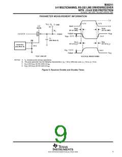
TEST CIRCUIT
C includes probe and jig capacitance.
L
VOLTAGE WAVEFORMS
NOTES: A.
B. The pulse generator has the following characteristics: Z = 50 Ω, 50% duty cycle, t ≤ 10 ns, t ≤ 10 ns.
O
r
f
Figure 4. Receiver Propagation Delay Times
8
POST OFFICE BOX 655303 • DALLAS, TEXAS 75265

 TI [ TEXAS INSTRUMENTS ]