ꢀ ꢁꢂ ꢃ ꢄꢄ
ꢅ ꢆꢇ ꢀ ꢈꢉꢊ ꢋꢌꢍ ꢁꢎꢎꢏꢉ ꢐꢑ ꢆꢃꢒ ꢃ ꢉ ꢋꢎꢏ ꢓꢐꢋ ꢇꢏ ꢐꢔꢐꢏ ꢌꢏ ꢋ ꢇ ꢏꢐ
ꢕ ꢋꢊ ꢍ ꢄ ꢅ ꢆꢖ ꢇ ꢏꢑ ꢓ ꢗꢐ ꢘ ꢊꢏ ꢌꢊ ꢋꢘ ꢎ
SLLS567E − MAY 2003 − REVISED JANUARY 2004
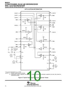
APPLICATION INFORMATION
capacitor selection
The capacitor type used for C1−C4 is not critical for proper operation. The MAX211 requires 0.1-µF capacitors,
although capacitors up to 10 µF can be used without harm. Ceramic dielectrics are suggested for the 0.1-µF
capacitors. When using the minimum recommended capacitor values, make sure the capacitance value does
not degrade excessively as the operating temperature varies. If in doubt, use capacitors with a larger (e.g., 2×)
nominal value. The capacitors’ effective series resistance (ESR), which usually rises at low temperatures,
influences the amount of ripple on V+ and V−.
Use larger capacitors (up to 10 µF) to reduce the output impedance at V+ and V−.
Bypass V
charge pumps, decouple V
capacitors (C1−C4).
to ground with at least 0.1 µF. In applications sensitive to power-supply noise generated by the
CC
to ground with a capacitor the same size as (or larger than) the charge-pump
CC
electrostatic discharge (ESD) protection
Texas Instruments MAX211 devices have standard ESD protection structures incorporated on the pins to
protect against electrostatic discharges encountered during assembly and handling. In addition, the RS232 bus
pins (driver outputs and receiver inputs) of these devices have an extra level of ESD protection. Advanced ESD
structures were designed to successfully protect these bus pins against ESD discharge of 15 kV when powered
down.
ESD test conditions
ESD testing is stringently performed by TI, based on various conditions and procedures. Please contact TI for
a reliability report that documents test setup, methodology, and results.
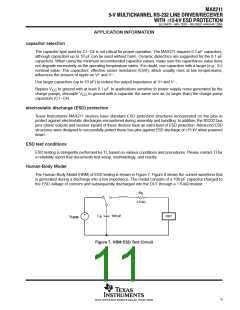
Human-Body Model
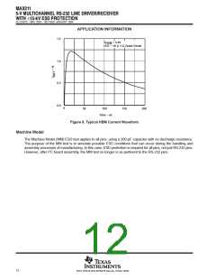
The Human-Body Model (HBM) of ESD testing is shown in Figure 7. Figure 8 shows the current waveform that
is generated during a discharge into a low impedance. The model consists of a 100-pF capacitor charged to
the ESD voltage of concern and subsequently discharged into the DUT through a 1.5-kΩ resistor.
R
D
1.5 kΩ
+
−
100 pF
C
DUT
V
HBM
S
Figure 7. HBM ESD Test Circuit
11
POST OFFICE BOX 655303 • DALLAS, TEXAS 75265

 TI [ TEXAS INSTRUMENTS ]