DM385, DM388
www.ti.com
SPRS821D –MARCH 2013–REVISED DECEMBER 2013
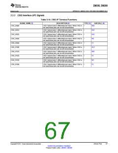
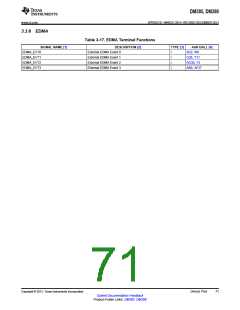
3.3.3 CSI2 Interface (I/F) Signals
Table 3-14. CSI2 I/F Terminal Functions
SIGNAL NAME [1]
DESCRIPTION [2]
TYPE [3]
AAR BALL [4]
AB2
CSI2_DX[0]
CSI2_DX[1]
CSI2_DX[2]
CSI2_DX[3]
CSI2_DX[4]
CSI2_DY[0]
CSI2_DY[1]
CSI2_DY[2]
CSI2_DY[3]
CSI2_DY[4]
CSI2 Camera lane 0 differential pair input. When CSI2 is
not used these pins can be left unconnected.
I
CSI2 Camera lane 1 differential pair input. When CSI2 is
not used these pins can be left unconnected.
I
I
I
I
I
I
I
I
I
AA1
AA2
W2
V1
CSI2 Camera lane 2 differential pair input. When CSI2 is
not used these pins can be left unconnected.
CSI2 Camera lane 3 differential pair input. When CSI2 is
not used these pins can be left unconnected.
CSI2 Camera lane 4 differential pair input. When CSI2 is
not used these pins can be left unconnected.
CSI2 Camera lane 0 differential pair input. When CSI2 is
not used these pins can be left unconnected.
AC2
AB1
Y2
CSI2 Camera lane 1 differential pair input. When CSI2 is
not used these pins can be left unconnected.
CSI2 Camera lane 2 differential pair input. When CSI2 is
not used these pins can be left unconnected.
CSI2 Camera lane 3 differential pair input. When CSI2 is
not used these pins can be left unconnected.
W1
V2
CSI2 Camera lane 4 differential pair input. When CSI2 is
not used these pins can be left unconnected.
Copyright © 2013, Texas Instruments Incorporated
Device Pins
67
Submit Documentation Feedback
Product Folder Links: DM385 DM388

 TI [ TEXAS INSTRUMENTS ]