DM385, DM388
www.ti.com
SPRS821D –MARCH 2013–REVISED DECEMBER 2013
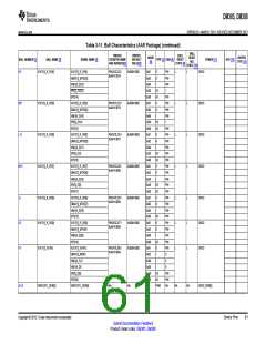
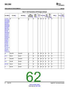
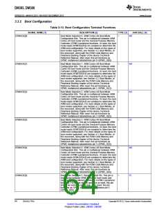
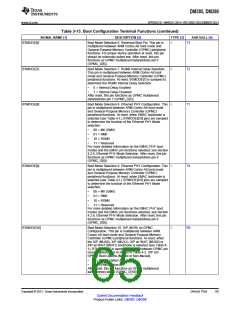
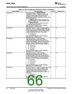
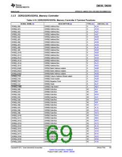
Table 3-13. Boot Configuration Terminal Functions (continued)
SIGNAL NAME [1]
DESCRIPTION [2]
TYPE [3]
AAR BALL [4]
BTMODE[6]
Boot Mode Selection 6. Reserved Boot Pin. This pin is
multiplexed between ARM Cortex-A8 boot mode and
General-Purpose Memory Controller (GPMC) peripheral
functions. For proper device operation at reset, this pin
should be externally pulled low. After reset, this pin
functions as GPMC multiplexed data/address pin 6
(GPMC_D[6]).
I
T3
T2
BTMODE[7]
Boot Mode Selection 7. RGMII Internal Delay Selection.
This pin is multiplexed between ARM Cortex-A8 boot
mode and General-Purpose Memory Controller (GPMC)
peripheral functions. At reset, BTMODE[7] is sampled to
determine the RGMII Internal Delay Selection:
I
•
•
0 = Internal Delay Enabled
1 = Internal Delay Disabled
After reset, this pin functions as GPMC multiplexed
data/address pin 7 (GPMC_D[7]).
BTMODE[8]
Boot Mode Selection 8. Ethernet PHY Configuration. This
pin is multiplexed between ARM Cortex-A8 boot mode
and General-Purpose Memory Controller (GPMC)
peripheral functions. At reset, when EMAC bootmode is
selected (see Table 4-1), BTMODE[9:8] pins are sampled
to determine the function of the Ethernet PHY Mode
selection:
I
T1
T8
R6
•
•
•
•
00 = MII (GMII)
01 = RMII
10 = RGMII
11 = Reserved
For more detailed information on the EMAC PHY boot
modes and the EMAC pin functions selected, see Section
4.2.6, Ethernet PHY Mode Selection. After reset, this pin
functions as GPMC multiplexed data/address pin 8
(GPMC_D[8]).
BTMODE[9]
Boot Mode Selection 9. Ethernet PHY Configuration. This
pin is multiplexed between ARM Cortex-A8 boot mode
and General-Purpose Memory Controller (GPMC)
peripheral functions. At reset, when EMAC bootmode is
selected (see Table 4-1), BTMODE[9:8] pins are sampled
to determine the function of the Ethernet PHY Mode
selection:
I
•
•
•
•
00 = MII (GMII)
01 = RMII
10 = RGMII
11 = Reserved
For more detailed information on the EMAC PHY boot
modes and the EMAC pin functions selected, see Section
4.2.6, Ethernet PHY Mode Selection. After reset, this pin
functions as GPMC multiplexed data/address pin 9
(GPMC_D[9]).
BTMODE[10]
Boot Mode Selection 10. XIP (NOR) on GPMC
I
Configuration. This pin is multiplexed between ARM
Cortex-A8 boot mode and General-Purpose Memory
Controller (GPMC) peripheral functions. At reset, when
the XIP (MUX0), XIP (MUX1), XIP w/ WAiT (MUX0) or
XIP w/ WAiT (MUX1) bootmode is selected (see Table 4-
1), BTMODE[10] is sampled to select between GPMC pin
muxing options A or B shown in Table 4-2, XIP (on
GPMC) Boot Options [Muxed or Non-Muxed].
•
•
0 = GPMC Option A
1 = GPMC Option B
After reset, this pin functions as GPMC multiplexed
data/address pin 10 (GPMC_D[10]).
Copyright © 2013, Texas Instruments Incorporated
Device Pins
65
Submit Documentation Feedback
Product Folder Links: DM385 DM388

 TI [ TEXAS INSTRUMENTS ]