DM385, DM388
www.ti.com
SPRS821D –MARCH 2013–REVISED DECEMBER 2013
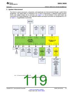
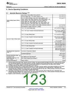
5 System Interconnect
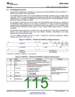
The device’s various processors, subsystems, and peripherals are interconnected through a switch fabric
architecture. The switch fabric is composed of an L3 and L4 interconnect, a switched central resource
(SCR), and multiple bridges (for an overview, see Figure 5-1). Not all Initiators in the switch fabric are
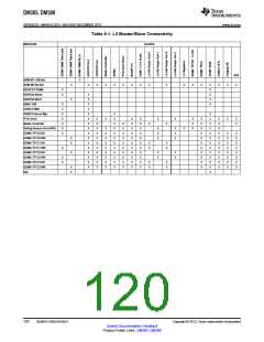
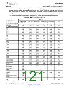
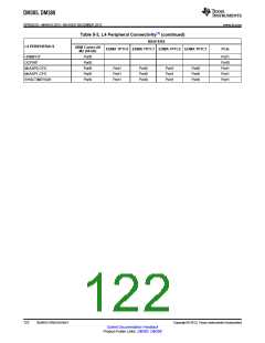
connected to all Target peripherals. The supported initiator and target connections are designated by a "X"
in Table 5-1, Target/Initiator Connectivity.
EDMATC RD 0/1
EDMATC WR 0/1
L3F
Initiators
L3F
Initiators
L3F
Initiators
L3F
Initiators
EDMATC RD 2/3
EDMATC WR 2/3
HDVICP2
HDVPSS (2 I/F)
ISS
PCIe
MEDIACTL
EMAC SW
FD
DAP
JTAG
USB2.0 (2 I/F)
ARM Cortex
A8
64b
128b
64b
128b
128b
32b
32b
1 I/F
8 I/F
4 I/F
2 I/F
3 I/F
3 I/F
L3F/L3Mid
Interconnect
200 MHz (Note 1)
L3S Interconnect
100 MHz (Note 1)
2 I/F
1 I/F
128b
3 I/F
64b
10 I/F
32b
5 I/F
2 I/F
2 I/F
32b
128b
128b
32b
32b
DMM
L3F
Targets
L3F
Targets
L3F
Targets
L3S
Targets
L4F
Interconnect
L4S
Interconnect
ISS
MMCSD 2
HDVICP 2 CFG
EDMATC 0/1/2/3
EDMACC
HDVICP2 SL2
PCIe
MEDIACTL
OCMC SRAM
MCASP 0/1 Data
GPMC
HDMI
200MHz
100MHz
DDR
(Note 1)
(Note1)
42 I/F
32b
USB
DEBUGSS
1 I/F
32b
L4F Targets
L4S Targets
EMAC SW
UART 0/1/2
I2C 0/1/2/3
DMTimer 1/2/3/4/5/6/7/8
SPI 0/1/2/3
GPIO 0/1/2/3
McASP 0/1 CFG
MMCSD 0/1
ELM
RTC
WDT 0/1
Mailbox
Spinlock
HDVPSS
HDMIPHY
PLLSS
Control Module
PRCM
SmartReflex 0/1
OCPWP
SYNCTIMER32K
Note 1: The frequencies specified are for 100% OPP.
Figure 5-1. System Interconnect
Copyright © 2013, Texas Instruments Incorporated
System Interconnect
119
Submit Documentation Feedback
Product Folder Links: DM385 DM388

 TI [ TEXAS INSTRUMENTS ]