DLPA2000
ZHCSCO5B –JUNE 2014–REVISED FEBRUARY 2018
www.ti.com.cn
Typical Mobile Sensing Application (continued)
0/F5:
.-@
/NGVMKV
($)&XT&+$+&B
<TZKV&
9GSGMKRKSX
'$,&B
'$'&B
;XNKV
?YUUQOKW
'$'#B
>KM
B5:
?D?<C>
<>;6F;:
;S%;LL
B00
'$,&B
'$,?&B
8?F5:
B810
<>;6F;:
A?.
&')$"
/1ꢀ
&')$" #
<>;6F;:
?<5Fꢀ
>10
0KXKIXTV
-0/
&*&
28-?4
/YVVKSX
?KSWK
?<5F'
&*&
>1?1@E
5:@E
28-?4"&
?0>-9
(,*1/01/*+22/1
<->7E
4;?@F5>=
@>53F5:
5QQYROSGXOTS&
;UXOIW
.5-?"&>?@"&;2?
)
810F?18ꢁ(
/9<F<C9
&')%!#
@>53F;A@&ꢁ(
7K[UGJ
/9<F;A@
<GVGQQKQ&>3.&5%2&ꢁ(,
?0&
/GVJ
08<(ꢀ'ꢀ:5>
CB3-
ꢁCB3-
00>&090
090
@NKVROWXTV
5(/
?YH#8B0?&0-@-
8<?0>&/@>8
'$,?&B
'$'&B
B5;
.QYKXTTXN
B//F5:@2
B//F28?4
B/;>1
<VTPKIXOTS&
;UXOIW
:5>&
0KXKIXTV
$&%ꢀ3ꢀ$.0-,ꢁ+1
08<\&/NOU&?KX
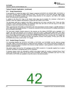
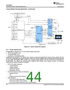
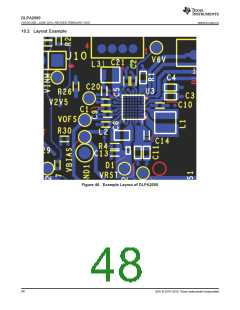
Figure 44. Typical Application Diagram
8.3.1 Design Requirements
All applications using the DLP 0.2-inch WVGA chipset require the:
•
•
•
DLPC150 controller, and
DLPA2000 PMIC, and
DLP2010 or DLP2010NIR DMD
components for operation. The system also requires an external parallel flash memory device loaded with the
DLPC150 configuration and support firmware. DLPC150 does the digital image processing and formats the data
for the DMD. DLPA2000 PMIC provides the needed analog functions for the DLPC150 and DLP2010 or
DLP2010NIR. The chipset has several system interfaces and requires some support circuitry. The following
interfaces and support circuitry are required:
•
DLPC150 system interfaces:
–
–
–
–
Control interface
Trigger interface
Input data interface
Illumination interface
•
•
DLPC150 support circuitry and interfaces:
–
–
–
Reference clock
PLL
Program memory flash interface
DMD interfaces:
–
–
–
DLPC150 to DMD digital data
DLPC150 to DMD control interface
DLPC150 to DMD micromirror reset control interface
44
Copyright © 2014–2018, Texas Instruments Incorporated

 TI [ TEXAS INSTRUMENTS ]