DLPA2000
ZHCSCO5B –JUNE 2014–REVISED FEBRUARY 2018
www.ti.com.cn
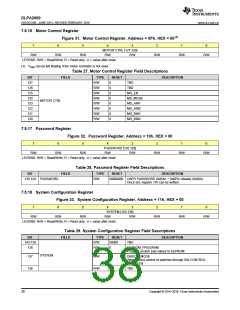
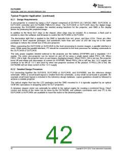
7.5.16 Motor Control Register
Figure 31. Motor Control Register, Address = 0Fh, HEX = 00(1)
7
6
5
4
3
2
1
0
MOTOR CTRL [127:120]
R/W R/W
R/W
R/W
R/W
R/W
R/W
R/W
LEGEND: R/W = Read/Write; R = Read only; -n = value after reset.
(1) VINM can be left floating if the motor controller is not used.
Table 27. Motor Control Register Field Descriptions
BIT
127
126
125
124
123
122
121
120
FIELD
TYPE
R/W
RESET
DESCRIPTION
0
0
0
0
0
0
0
0
TBD
R/W
R/W
R/W
R/W
R/W
R/W
R/W
TBD
MD_EN
MD_MODE
MD_AIN1
MD_AIN2
MD_BIN1
MD_BIN2
MOTOR CTRL
7.5.17 Password Register
Figure 32. Password Register, Address = 10h, HEX = 00
7
6
5
4
3
2
1
0
PASSWORD [135:128]
R/W R/W
R/W
R/W
R/W
R/W
R/W
R/W
LEGEND: R/W = Read/Write; R = Read only; -n = value after reset
Table 28. Password Register Field Descriptions
BIT
FIELD
TYPE
R/W
RESET
DESCRIPTION
135:128 PASSWORD
00000000 USER PASSWORD (0xBAh + 0xBEh) disable (0x00h).
Once set, register 11h can be written.
7.5.18 System Configuration Register
Figure 33. System Configuration Register, Address = 11h, HEX = 00
7
6
5
4
3
2
1
0
SYSTEM [143:136]
R/W R/W
R/W
R/W
R/W
R/W
R/W
R/W
LEGEND: R/W = Read/Write; R = Read only; -n = value after reset.
Table 29. System Configuration Register Field Descriptions
BIT
143:139
138
FIELD
TYPE
R/W
RESET
00000
DESCRIPTION
TBD
R/W
0
EEPROM_PROGRAM
Program scratch pad values to EEPROM
SYSTEM
137
136
R/W
0
DIRECT_MODE
Allows direct control of switches through SW CONTROL
REGISTER
R/W
0
TBD
38
Copyright © 2014–2018, Texas Instruments Incorporated

 TI [ TEXAS INSTRUMENTS ]