CC2640R2L
ZHCSRK4A –APRIL 2020 –REVISED SEPTEMBER 2020
www.ti.com.cn
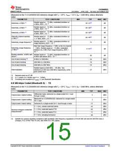
8.11 1-Mbps GFSK (Bluetooth low energy) –TX
Measured on the TI CC2650EM-5XD reference design with Tc = 25°C, VDDS = 3.0 V, fRF = 2440 MHz, unless otherwise
noted.
PARAMETER
TEST CONDITIONS
MIN
TYP
MAX UNIT
Differential mode, delivered to a single-ended 50-Ωload
through a balun
Output power, highest setting
5
dBm
Measured on CC2650EM-4XS, delivered to a single-ended
50-Ωload
Output power, highest setting
Output power, lowest setting
2
dBm
dBm
dBm
dBm
dBm
dBm
Delivered to a single-ended 50-Ωload through a balun
f < 1 GHz, outside restricted bands
f < 1 GHz, restricted bands ETSI
–21
–43
–65
–71
–46
Spurious emission conducted
measurement(1)
f < 1 GHz, restricted bands FCC
f > 1 GHz, including harmonics
(1) Suitable for systems targeting compliance with worldwide radio-frequency regulations ETSI EN 300 328 and EN 300 440 Class 2
(Europe), FCC CFR47 Part 15 (US), and ARIB STD-T66 (Japan).
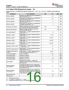
8.12 2-Mbps GFSK (Bluetooth 5) –RX
Measured on the TI CC2650EM-5XD reference design with Tc = 25°C, VDDS = 3.0 V, fRF = 2440 MHz, unless otherwise
noted.
PARAMETER
TEST CONDITIONS
MIN
TYP
MAX UNIT
Differential mode. Measured at the CC2650EM-5XD
SMA connector, BER = 10–3
Receiver sensitivity
dBm
–90
Differential mode. Measured at the CC2650EM-5XD
SMA connector, BER = 10–3
Receiver saturation
3
dBm
500 kHz
1000 ppm
dB
Difference between the incoming carrier frequency and
the internally generated carrier frequency
Frequency error tolerance
Data rate error tolerance
Co-channel rejection(1)
–300
Difference between incoming data rate and the
internally generated data rate
–1000
Wanted signal at –67 dBm, modulated interferer in
–7
8 / 4(2)
channel, BER = 10–3
Wanted signal at –67 dBm, modulated interferer at
±2 MHz, Image frequency is at –2 MHz BER = 10–3
Selectivity, ±2 MHz(1)
Selectivity, ±4 MHz(1)
Selectivity, ±6 MHz(1)
dB
dB
dB
dB
dB
Wanted signal at –67 dBm, modulated interferer at
31 / 26(2)
37 / 38(2)
37 / 36(2)
4
±4 MHz, BER = 10–3
Wanted signal at –67 dBm, modulated interferer at
±6 MHz, BER = 10–3
Alternate channel rejection,
±7 MHz(1)
Wanted signal at –67 dBm, modulated interferer at ≥
±7 MHz, BER = 10–3
Wanted signal at –67 dBm, modulated interferer at
Selectivity, image frequency(1)
image frequency, BER = 10–3
Note that Image frequency + 2 MHz is the Co-channel.
Wanted signal at –67 dBm, modulated interferer at
±2 MHz from image frequency, BER = 10–3
Selectivity, image frequency
±2 MHz(1)
–7 / 26(2)
dB
Out-of-band blocking(3)
Out-of-band blocking
Out-of-band blocking
Out-of-band blocking
30 MHz to 2000 MHz
2003 MHz to 2399 MHz
2484 MHz to 2997 MHz
3000 MHz to 12.75 GHz
dBm
dBm
dBm
dBm
–33
–15
–12
–10
Wanted signal at 2402 MHz, –64 dBm. Two interferers
at 2408 and 2414 MHz respectively, at the given power
level
Intermodulation
dBm
–45
(1) Numbers given as I/C dB.
Copyright © 2023 Texas Instruments Incorporated
Submit Document Feedback
17

 TI [ TEXAS INSTRUMENTS ]