CC2640R2L
ZHCSRK4A –APRIL 2020 –REVISED SEPTEMBER 2020
www.ti.com.cn
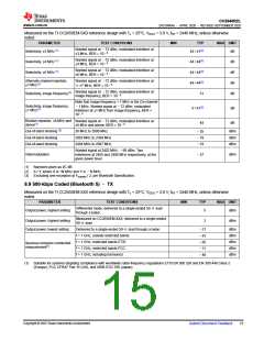
8.5 General Characteristics
Tc = 25°C, VDDS = 3.0 V, unless otherwise noted.
PARAMETER
TEST CONDITIONS
MIN
TYP
MAX
UNIT
FLASH MEMORY
Supported flash erase cycles before
failure(1)
100
k Cycles
Maximum number of write operations
per row before erase(2)
write
operations
83
Years at
105°C
Flash retention
105°C
11.4
Flash page/sector erase current
Flash page/sector size
Flash write current
Average delta current
12.6
4
mA
KB
mA
ms
µs
Average delta current, 4 bytes at a time
4 bytes at a time
8.15
8
Flash page/sector erase time(3)
Flash write time(3)
8
(1) Aborting flash during erase or program modes is not a safe operation.
(2) Each row is 2048 bits (or 256 Bytes) wide.
(3) This number is dependent on Flash aging and will increase over time and erase cycles.
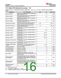
8.6 125-kbps Coded (Bluetooth 5) –RX
Measured on the TI CC2650EM-5XD reference design with Tc = 25°C, VDDS = 3.0 V, fRF = 2440 MHz, unless otherwise
noted.
PARAMETER
TEST CONDITIONS
MIN
TYP
MAX UNIT
Differential mode. Measured at the CC2650EM-5XD
SMA connector, BER = 10–3
Receiver sensitivity
dBm
–103
Differential mode. Measured at the CC2650EM-5XD
SMA connector, BER = 10–3
Receiver saturation
>5
dBm
310 kHz
260 ppm
140 ppm
dB
Difference between the incoming carrier frequency
and the internally generated carrier frequency
Frequency error tolerance
Data rate error tolerance
Data rate error tolerance
Co-channel rejection (1)
Selectivity, ±1 MHz (1)
–260
–260
–140
Difference between incoming data rate and the
internally generated data rate (37-byte packets)
Difference between incoming data rate and the
internally generated data rate (255-byte packets)
Wanted signal at –79 dBm, modulated interferer in
–3
9 / 5(2)
channel, BER = 10–3
Wanted signal at –79 dBm, modulated interferer at
dB
±1 MHz, BER = 10–3
Wanted signal at –79 dBm, modulated interferer at
±2 MHz, Image frequency is at –2 MHz, BER = 10–3
Selectivity, ±2 MHz (1)
Selectivity, ±3 MHz (1)
Selectivity, ±4 MHz (1)
Selectivity, ±6 MHz (1)
43 / 32(2)
47 / 42(2)
46 / 47(2)
49 / 46(2)
50 / 47(2)
32
dB
dB
dB
dB
dB
dB
Wanted signal at –79 dBm, modulated interferer at
±3 MHz, BER = 10–3
Wanted signal at –79 dBm, modulated interferer at
±4 MHz, BER = 10–3
Wanted signal at –79 dBm, modulated interferer at
±6 MHz, BER = 10–3
Alternate channel rejection,
±7 MHz(1)
Wanted signal at –79 dBm, modulated interferer at
≥±7 MHz, BER = 10–3
Wanted signal at –79 dBm, modulated interferer at
Selectivity, image frequency(1)
image frequency, BER = 10–3
Note that Image frequency + 1 MHz is the Co-channel
–1 MHz. Wanted signal at –79 dBm, modulated
interferer at ±1 MHz from image frequency, BER =
10–3
Selectivity, image frequency
±1 MHz(1)
5 / 32(2)
dB
Copyright © 2023 Texas Instruments Incorporated
Submit Document Feedback
13

 TI [ TEXAS INSTRUMENTS ]