CC1110Fx / CC1111Fx
12.1.6
Timer Tick Generation
The XDATA memory locations 0xFDA2 -
0xFEFF (350 bytes) will lose all data when
PM2 or PM3 is entered. These locations will
contain undefined data when active mode is
re-entered.
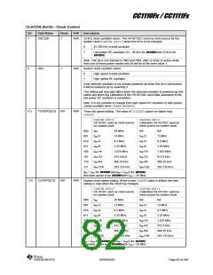
The power management controller generates
a tick or enable signal for the peripheral
timers, thus acting as a prescaler for the
timers. This is a global clock division for Timer
1, Timer 2, Timer 3, and Timer 4. The tick
speed is programmed from 0.203 to 26 MHz
for CC1110Fx assuming a 26 MHz crystal or
from 0.1875 to 24 MHz for CC1111Fx by setting
the CLKCON.TICKSPDregister appropriately.
The registers which retain their contents are
the CPU registers, peripheral registers and RF
registers, unless otherwise specified for a
given register bit field. Switching to power
modes PM2 and PM3 appears transparent to
software with the following exception:
Note: CLKCON.TICKSPD cannot be set
higher than CLKCON.CLKSPD.
Watchdog timer 15-bit counter is reset
to 0x0000 when entering PM2 or PM3
HS RCOSC calibration value gets reset
to its default value upon waking up from
PM2 and PM3.
12.1.7
Data Retention
In PM2 and PM3, power is removed from most
of the internal circuitry. However, parts of
SRAM will retain its contents. The content of
internal registers is also retained in PM2 and
PM3, with some exceptions (see Table 31,
Table 32, and Table 33).
12.1.8
I/O and Radio
I/O port pins P1_0 and P1_1 do not have
internal pull-up/pull-down resistors. These pins
should therefore be set as outputs or pulled
high/low externally to avoid leakage current.
The XDATA memory locations 0xF000 -
0xFFFF (4096 bytes) retain data in PM2 and
PM3. Please note the following exception:
To save power, the radio should be turned off
when it is not used.
12.2 Reset
Brown Out Detector (BOD) operating on the
regulated 1.8 V digital power supply only, The
BOD will protect the memory contents during
supply voltage variations which cause the
regulated 1.8 V power to drop below the
minimum level required by flash memory and
SRAM.
The CC1110Fx/CC1111Fx has four reset sources.
The following events generate a reset:
Forcing RESET_N input pin low
A power-on reset condition
A brown-out reset condition
Watchdog timer reset condition
When power is initially applied to the
CC1110Fx/CC1111Fx the Power On Reset (POR)
and Brown Out Detector (BOD) will hold the
device in reset state until the supply voltage
reaches above the Power On Reset and
Brown Out voltages.
The initial conditions after a reset are as
follows:
I/O pins are configured as inputs with
pull-up, except P1_0 and P1_1.
CPU program counter is loaded with
0x0000 and program execution starts at
this address
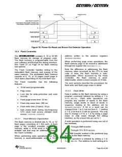
Figure 19 shows the POR/BOD operation with
the 1.8 V (typical) regulated supply voltage
together with the active low reset signals
BOD_RESET and POR_RESET shown in the
bottom of the figure (note that these signals
are not available but are included on the figure
for illustration purposes).
All peripheral registers are initialized to
their reset values (refer to register
descriptions)
Watchdog timer is disabled
The cause of the last reset can read from the
register bits SLEEP.RST. It should be noted
that a BOD reset will be read as a POR reset.
12.2.1
Power On Reset and Brown Out
Detector
The CC1110Fx/CC1111Fx includes a Power On
Reset (POR) providing correct initialization
during device power-on. Also included is a
SWRS033H
Page 83 of 246

 TI [ TEXAS INSTRUMENTS ]