CC1110Fx / CC1111Fx
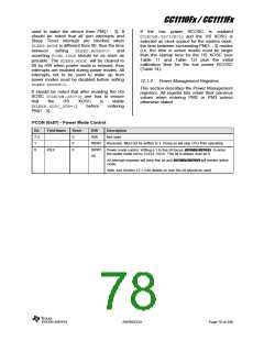
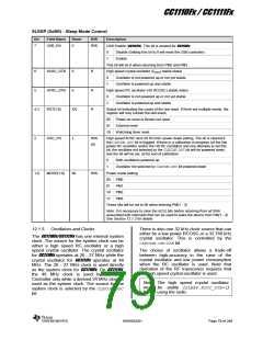
SLEEP (0xBE) - Sleep Mode Control
Bit
Field Name
Reset
R/W
Description
USB Enable (CC1111Fx). This bit is unused for CC1110Fx
7
USB_EN
0
R/W
0
1
Disable (Setting this bit to 0 will reset the USB controller)
Enable
This bit will be 0 when returning from PM2 and PM3
6
XOSC_STB
HFRC_STB
RST[1:0]
0
R
R
R
High speed crystal oscillator (fXOSC) stable status
0
1
Oscillator is not powered up or not yet stable
Oscillator is powered up and stable
5
0
High speed RC oscillator (HS RCOSC) stable status
0
1
Oscillator is not powered up or not yet stable
Oscillator is powered up and stable
4:3
XX
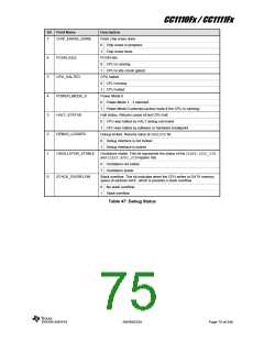
Status bit indicating the cause of the last reset. If there are multiple resets, the
register will only contain the last event.
00
01
10
Power-on reset or Brown-out reset
External reset
Watchdog timer reset
2
OSC_PD
1
R/W
H0
High speed XOSC and HS RCOSC power down setting. The bit is cleared if
the CLKCON.OSCbit is toggled. If there is a calibration in progress (of the low
power RC oscillator and/or the HS RC oscillator) and one attempts to set this
bit, the oscillator not selected by the CLKCON.OSCbit will be powered down,
and the bit will be set, at the end of calibration.
0
1
Both oscillators powered up
Oscillator not selected by CLKCON.OSCbit powered down
1:0
MODE[1:0]
00
R/W
Power mode setting
00
01
10
11
PM0
PM1
PM2
PM3
These bits will be set to 00 when entering PM{1 - 3}
Note: It is necessary to clear the MODEbits before returning from all ISRs
associated with interrupts that can be used to wake the device from PM{1 - 3}.
See Section 12.1.3 for details
12.1.5
Oscillators and Clocks
There is also one 32 kHz clock source that can
either be a low power RCOSC or a 32.768 kHz
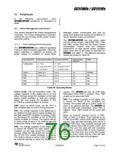
The CC1110Fx/CC1111Fx has one internal system
clock. The source for the system clock can be
either a high speed RC oscillator or a high
speed crystal oscillator. The crystal oscillator
for CC1110Fx operates at 26 - 27 MHz while the
crystal oscillator for CC1111Fx operates at 48
MHz. The 26 - 27 MHz clock is used directly
as the system clock for CC1110Fx. On CC1111Fx,
the 48 MHz clock is used by the USB
Controller only while a derived 24 MHz clock is
used as the system clock. The source for the
system clock is selected by the CLKCON.OSC
bit.
crystal oscillator. This is controlled by the
CLKCON.OSC32Kbit.
The choice of oscillator allows a trade-off
between high-accuracy in the case of the
crystal oscillator and low power consumption
when the RC oscillator is used. Note that
operation of the RF transceiver requires that
the high speed crystal oscillator is used.
Note: The high speed crystal oscillator
must be stable (SLEEP.XOSC_STB=1)
before using the radio.
SWRS033H
Page 79 of 246

 TI [ TEXAS INSTRUMENTS ]