CC1110Fx / CC1111Fx
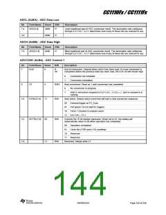
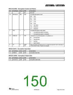
RNDL (0xBC) - Random Number Generator Data Low Byte
Bit
Field Name
Reset
R/W
Description
[7:0]
RNDL[7:0]
0xFF
R/W
Random value/seed or CRC result, low byte
When used for random number generation writing this register twice will seed the
random number generator. Writing to this register copies the 8 LSBs of the LFSR
to the 8 MSBs and replaces the 8 LSBs with the data value written.
The value returned when reading from this register is the 8 LSBs of the LFSR.
When used for random number generation, reading this register returns the 8 LSBs
of the random number. When used for CRC calculations, reading this register
returns the 8 LSBs of the CRC result.
RNDH (0xBD) - Random Number Generator Data High Byte
Bit
Field Name
Reset
R/W
Description
[7:0]
RNDH[7:0]
0xFF
R/W
Random value or CRC result/input data, high byte
When written, a CRC16 calculation will be triggered, and the data value written is
processed starting with the MSB bit.
The value returned when reading from this register is the 8 MSBs of the LFSR.
When used for random number generation, reading this register returns the 8
MSBs of the random number. When used for CRC calculations, reading this
register returns the 8 MSBs of the CRC result.
12.12 AES Coprocessor
12.12.2 Key and IV
The CC1110Fx/CC1111Fx data encryption is
performed using a dedicated coprocessor
which supports the Advanced Encryption
Standard, AES. The coprocessor allows
encryption/decryption to be performed with
minimal CPU usage.
Before a key or IV/nonce load starts, an
appropriate load key or IV/nonce command
must be issued to the coprocessor. When
loading the IV it is important to also set the
correct mode.
The coprocessor has the following features:
A key load or IV load operation aborts any
processing that could be running.
ECB, CBC, CFB, OFB, CTR, and
CBC- MAC modes.
The key, once loaded, stays valid until a key
reload takes place.
Hardware support for CCM mode
128-bits key and IV/Nonce
The IV must be downloaded before the
beginning of each message (not block).
DMA transfer trigger capability
Both key and IV are cleared by a reset of the
device and when PM2 or PM3 are entered.
12.12.1 AES Operation
To encrypt
procedure must be followed:
a
message, the following
12.12.3 Padding of Input Data
AES works on blocks of 128 bits. If a block
contains less than 128 bits, it must be
padded with zeros when written to the
coprocessor.
Load key
Load initialization vector (IV)/nonce
Download and upload data for
encryption/decryption.
12.12.4 Interface to CPU
The AES coprocessor works on blocks of
128 bits. A block of data is loaded into the
coprocessor, encryption is performed, and
the result must be read out before the next
block can be processed. Before each block
load, a dedicated start command must be
sent to the coprocessor.
The
CPU
communicates
with
the
coprocessor using three SFRs:
ENCCS, Encryption control and status
register
ENCDI, Encryption input register
ENCDO, Encryption output register
SWRS033H
Page 148 of 246

 TI [ TEXAS INSTRUMENTS ]