CC1110Fx / CC1111Fx
Parameter
Min
Typ
Max
Unit
Condition
System clock running at 26 MHz or 24 MHz.
Active mode with
radio in TX,
433 MHz
Digital regulator on. High speed crystal oscillator and low power
RCOSC running. Radio in TX mode
33.5
20
mA
mA
mA
10 dBm output power (PA_TABLE0=0xC0)
0 dBm output power (PA_TABLE0=0x60)
−6 dBm output power (PA_TABLE0=0x2A)
System clock running at 26 MHz or 24 MHz.
19
Active mode with
radio in TX,
868, 915 MHz
Digital regulator on. High speed crystal oscillator and low power
RCOSC running. Radio in TX mode
36.2
mA
10 dBm output power (PA_TABLE0=0xC2). See Table 7 for typical
variation over operating conditions
21
20
mA
mA
mA
0 dBm output power (PA_TABLE0=0x50)
−6 dBm output power (PA_TABLE0=0x2B)
Power mode 0
Power mode 1
4.3
Same as active mode, but the CPU is not running (see 12.1.2.2 for
details). System clock at 26 MHz or 24 MHz
220
Digital regulator on. HS RCOSC and high speed crystal oscillator off.
32.768 kHz XOSC or low power RCOSC running (see 12.1.2.3 for
details)
A
Power mode 2
Power mode 3
0.5
0.3
µA
µA
Digital regulator off. HS RCOSC and high speed crystal oscillator off.
Low power RCOSC running (see 12.1.2.4 for details)
1.0
Digital regulator off. No crystal oscillators or RC oscillators are
running (see 12.1.2.5 for details)
Peripheral
Current
Add to the figures above if the peripheral unit is activated
Consumption
Timer 1
Timer 2
Timer 3
Timer 4
ADC
2.7
1.3
1.6
2
When running
When running
When running
When running
During conversion
A/MHz
A/MHz
A/MHz
A/MHz
mA
1.2
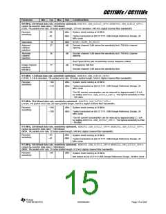
Table 6: Current Consumption
SWRS033H
Page 11 of 246

 TI [ TEXAS INSTRUMENTS ]