CC1110Fx / CC1111Fx
flexibility. The possibilities for address
increment/decrement are:
described in the previous section have to be
configured before a DMA channel can be
armed and activated. The parameters are not
configured directly through SFRs, but instead
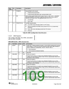
they are written in a special DMA configuration
data structure in memory. Each DMA channel
in use requires its own DMA configuration data
structure. The DMA configuration data
structure consists of eight bytes and is
described in Table 52. A DMA configuration
data structure may reside at any location in
unified memory space decided upon by the
user software, and the address location is
passed to the DMA controller through a set of
SFRs DMAxCFGH:DMAxCFGL (x is 0 or 1).
Once a channel has been armed, the DMA
controller will read the configuration data
structure for that channel, given by the
address in DMAxCFGH:DMAxCFGL.
Increment by zero. The address pointer
shall remain fixed after each byte/word
transfer.
Increment by one. The address pointer
shall increment one count after each
byte/word transfer.
Increment by two. The address pointer
shall increment two counts after each
byte/word transfer.
Decrement by one. The address pointer
shall decrement one count after each
byte/word transfer.
12.5.2.8 Interrupt Mask (IRQMASK)
If this bit is set to 1, the CPU interrupt flag
IRCON.DMAIF=1 will be asserted when the
transfer count is reached. An interrupt request
is being generated if IEN1.DMAIE=1.
It is important to note that the method for
specifying the start address for the DMA
configuration data structure differs between
DMA channel 0 and DMA channels 1 - 4 as
follows:
12.5.2.9 Mode 8 Setting (M8)
DMA0CFGH:DMA0CFGLgives the start address
for DMA channel
structure.
0
configuration data
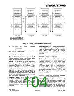
When variable length transfer count is used
(VLEN≠000 and VLEN≠111) this field
determines whether to use seven or eight bits
of the first byte in source data to determine the
transfer count. This configuration is only
applicable when doing byte transfers.
DMA1CFGH:DMA1CFGLgives the start address
for DMA channel 1 configuration data structure
followed by channel 2 - 4 configuration data
structures.
This means that the DMA controller expects
the DMA configuration data structures for DMA
channels 1 - 4 to lie in a contiguous area in
memory, starting at the address held in
DMA1CFGH:DMA1CFGL and consisting of 32
bytes.
12.5.2.10 DMA Priority (PRIORITY)
A DMA priority is associated with each DMA
channel. The DMA priority is used to
determine the winner in the case of multiple
simultaneous internal memory requests, and
whether the DMA memory access should have
priority or not over a simultaneous CPU
memory access. In case of an internal tie, a
round-robin scheme is used to ensure access
for all. There are three levels of DMA priority:
12.5.4
Aborting Transfers
Ongoing byte/word transfers or armed DMA
channels will be aborted using the DMAARM
register to disarm the DMA channel.
High: Highest internal priority. DMA access
One or more DMA channels are aborted by
writing a 1 to DMAARM.ABORTregister bit, and
at the same time select which DMA channels
to abort by setting the corresponding,
DMAARM.DMAARMn bits to 1. When setting
DMAARM.ABORT to 1, the DMAARM.DMAARMn
bits for non-aborted channels must be written
as 0.
will always prevail over CPU access.
Normal: Second highest internal priority.
Guarantees that DMA access prevails over
CPU on at least every second try.
Low: Lowest internal priority. DMA access will
always defer to a CPU access.
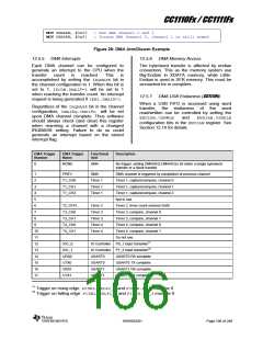
An example of DMA channel arm and disarm
is shown in Figure 28.
12.5.3
DMA Configuration Setup
The DMA channel parameters such as
address mode, transfer mode and priority
SWRS033H
Page 105 of 246

 TI [ TEXAS INSTRUMENTS ]