CC1110Fx / CC1111Fx
12.5 DMA Controller
12.5.1
DMA Operation
The CC1110Fx/CC1111Fx includes
a
direct
memory access (DMA) controller, which can
be used to relieve the 8051 CPU core of
handling data movement operations. Because
of this, the CC1110Fx/CC1111Fx can achieve high
overall performance with good power
efficiency. The DMA controller can move data
from a peripheral unit such as the ADC or RF
transceiver to memory with minimum CPU
intervention.
There are five DMA channels available in the
DMA controller numbered channel to
0
channel 4. Each DMA channel can move data
from one place within XDATA memory space
to another i.e. between XDATA locations.
Some CPU-specific SFRs reside inside the
CPU core and can only be accessed using the
SFR memory space and can therefore not be
accessed using DMA. These registers are
shown in gray in Table 30 on Page 47.
The DMA controller coordinates all DMA
transfers, ensuring that DMA requests are
prioritized appropriately relative to each other
and CPU memory access. The DMA controller
contains 5 programmable DMA channels for
data movement.
Note: In the following sections, an n in the
register name represent the channel
number 0, 1, 2, 3, or 4 if nothing else is
stated
The DMA controller controls data movement
over the entire XDATA memory space. Since
most of the SFRs are mapped into the XDATA
memory space these flexible DMA channels
can be used to unburden the CPU in
innovative ways, e.g. feed a USART and I2S
with data from memory, periodically transfer
samples between ADC and memory, transfer
data to and from USB FIFOs (CC1111Fx) etc.
Use of the DMA can also reduce system
power consumption by keeping the CPU idle
and not have it to wake up to move data to or
from a peripheral unit (see Section 12.1.2).
Note that Section 10.2.3.3 describes which
SFRs are not mapped into XDATA memory
space.
In order to use a DMA channel it must first be
configured as described in Sections 0 and
12.5.3.
Once a DMA channel has been configured it
must be armed before any transfers are
allowed to be initiated. A DMA channel is
armed by setting the appropriate bit DMAARMn
in the DMA Channel Arm register DMAARM.
When a DMA channel is armed it will start to
move data when the configured DMA trigger
event occurs. When a DMA channel is armed
a transfer will begin when the configured DMA
trigger event occurs. Note that it takes 9
system clocks from the arm bit is set until the
new configuration is loaded. While the new
configuration is being loaded, the DMA
channel will be able to accept triggers. This
will, however, not be the trigger stored in the
configuration data that are currently loaded,
but the trigger last used with this channel (after
a reset this will be trigger number 0, manual
trigger using the DMAREQ.DMAREQn bit). If n
channels are armed at the same time, loading
the configuration takes n x 9 clock cycles.
Channel 1 will first be ready, then channel 2,
and finally channel 0. It can not be assumed
that channel 1 is ready after 9 clock cycles,
channel 2 after 18 clock cycles, etc. To avoid
having the DMA channels starting to move
data on unwanted triggers when changing
configuration, a dummy configuration should
be loaded in-between configuration changes,
setting TRIG to 0. Alternatively, abort the
currently armed DMA channel before rearming
it. There are 30 possible DMA trigger events,
e.g. UART transfer, Timer overflow etc. The
DMA trigger events are listed in Table 51.
The main features of the DMA controller are
as follows:
Five independent DMA channels
Three configurable levels of DMA
channel priority
30 configurable trigger events
Independent control of source and
destination address
Single, block, and repeated transfer
modes
Supports variable transfer count length
by including the length field in the data
to be transferred
Can operate in either word-size or byte-
size mode
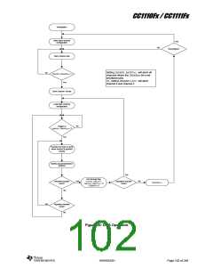
Figure 26 shows a DMA operation flow chart.
SWRS033H
Page 101 of 246

 TI [ TEXAS INSTRUMENTS ]