bq51010
bq51011
bq51013
SLVSAT9B –APRIL 2011–REVISED AUGUST 2011
www.ti.com
•
R3 = 13.98kΩ
where:
•
•
•
•
TCOLD = 0°C
THOT = 60°C
β = 4500
RO = 10kΩ
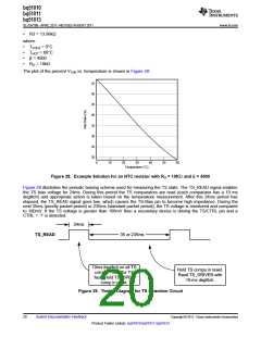
The plot of the percent VTSB vs. temperature is shown in Figure 28:
55
50
45
40
35
30
25
20
0
10
20
30
40
50
60
Temperature (°C)
Figure 28. Example Solution for an NTC resistor with RO = 10KΩ and β = 4500
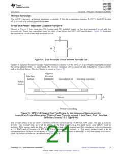
Figure 29 illustrates the periodic biasing scheme used for measuring the TS state. The TS_READ signal enables
the TS bias voltage for 24ms. During this period the TS comparators are read (each comparator has a 10 ms
deglitch) and appropriate action is taken based on the temperature measurement. After this 24ms period has
elapsed, the TS_READ signal goes low, which causes the TS-Bias pin to become high impedance. During the
next 35ms (priority packet period) or 235ms (standard packet period), the TS voltage is monitored and compared
to 100mV. If the TS voltage is greater than 100mV then a secondary device is driving the TS/CTRL pin and a
CTRL = ‘1’ is detected.
24ms
TS_READ
35 or 235ms
10ms deglitch on all TS
Hold TS comps in reset.
Read TS_DRIVEN with
10-ms deglitch.
comps – read for TS
fault. Hold TS_OPEN
comp in reset.
Figure 29. Timing Diagram for TS Detection Circuit
20
Submit Documentation Feedback
Copyright © 2011, Texas Instruments Incorporated
Product Folder Link(s): bq51010 bq51011 bq51013

 TI [ TEXAS INSTRUMENTS ]