bq51010
bq51011
bq51013
www.ti.com
SLVSAT9B –APRIL 2011–REVISED AUGUST 2011
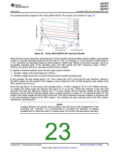
An example load-line analysis for the Vishay IWAS-4832FF-50 receiver coil is shown in Figure 33:
Fs=175
Fs=160
10
Fs=150
Fs=140
Fs=135
8
Fs=130
Fs=125
6
4
0.2
0.4
0.6
0.8
1.0
Load Current (A)
1A Load Step Droop
Ping Voltage
1A Load Operating Point
Figure 33. Vishay IWAS-4832FF-50 Load-Line Results
What this plot conveys about the operating point is that a specific load and rectifier target condition consequently
results in a specific operating frequency (for the type A1 TX). For example, at 1A the dynamic rectifier target is
5.15V. Therefore, the operating frequency will be between 150kHz and 160kHz in the above example. This is an
acceptable operating point. If the operating point ever falls outside the WPC frequency range (110kHz –
205kHz), the system will never converge and will become unstable.
In regards to transient analysis, there are two major points of interest:
1. Rectifier voltage at the ping frequency (175kHz).
2. Rectifier voltage droop from no load to full load at the constant operating point.
In this example, the ping voltage will be ~5V. This is above the UVLO of the bq5101x and; therefore, startup in
the WPC system can be ensured. If the voltage is near or below the UVLO at this frequency, then startup in the
WPC system may not occur.
If the max load step is 1A, the droop in this example will be ~1V with a voltage at 1A of ~5.5V (140kHz load-line).
To analyze the droop locate the load-line that starts at 7V at no-load. Follow this load-line to the max load
expected and take the difference between the 7V no-load voltage and the full-load voltage at that constant
frequency. Ensure that the full-load voltage at this constant frequency is above 5V. If it descends below 5V, the
output of the power supply will also droop to this level. This type of transient response analysis is necessary due
to the slow feedback response of the WPC system. This simulates the step response prior to the WPC system
adjusting the operating point.
NOTE
Coupling between the primary and secondary coils will worsen with misalignment of the
secondary coil. Therefore, it is recommended to re-analyze the load-lines at multiple
misalignments to determine where, in planar space, the receiver will discontinue operation.
Copyright © 2011, Texas Instruments Incorporated
Submit Documentation Feedback
23
Product Folder Link(s): bq51010 bq51011 bq51013

 TI [ TEXAS INSTRUMENTS ]