bq51010
bq51011
bq51013
www.ti.com
SLVSAT9B –APRIL 2011–REVISED AUGUST 2011
Thermal Protection
The bq5101x includes a thermal shutdown protection. If the die temperature reaches TJ(OFF), the LDO is shut
off to prevent any further power dissipation.
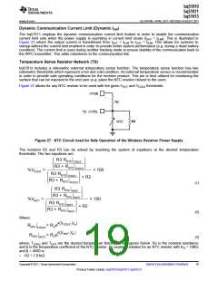
Series and Parallel Resonant Capacitor Selection
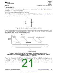
Shown in Figure 2, the capacitors C1 (series) and C2 (parallel) make up the dual resonant circuit with the
receiver coil. These two capacitors must be sized correctly per the WPC v1.0 specification. Figure 30 illustrates
the equivalent circuit of the dual resonant circuit:
C1
Ls’
C2
Figure 30. Dual Resonant Circuit with the Receiver Coil
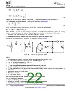
Section 4.2 (Power Receiver Design Requirements) in volume 1 of the WPC v1.0 specification highlights in detail
the sizing requirements. To summarize, the receiver designer will be required take inductance measurements
with a fixed test fixture. The test fixture is shown in Figure 31:
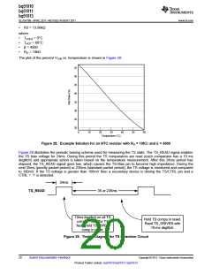
Figure 31. WPC v1.0 Receiver Coil Test Fixture for the Inductance Measurement Ls’
(copied from System Description Wireless Power Transfer, volume 1: Low Power, Part 1 Interface
Definition, Version 1.0.1, Figure 4-4)
The primary shield is to be 50mm x 50mm x 1mm of Ferrite material PC44 from TDK Corp. The gap dZ is to be
3.4mm. The receiver coil, as it will be placed in the final system (e.g. the back cover and battery must be
included if the system calls for this), is to be placed on top of this surface and the inductance is to be measured
at 1-V RMS and a frequency of 100 kHz. This measurement is termed Ls’. The same measurement is to be
repeated without the test fixture shown in Figure 9. This measurement is termed Ls or the free-space inductance.
Each capacitor can then be calculated using Equation 4:
Copyright © 2011, Texas Instruments Incorporated
Submit Documentation Feedback
21
Product Folder Link(s): bq51010 bq51011 bq51013

 TI [ TEXAS INSTRUMENTS ]