bq51010
bq51011
bq51013
SLVSAT9B –APRIL 2011–REVISED AUGUST 2011
www.ti.com
ù-1
2
)
'
C1 = f × 2p × LS
é
ë
(
S
ê
ú
û
é
ù-1
ú
2
1
ê
C2 = f × 2p × L -
(
)
D
S
ê
ú
C1
(4)
(5)
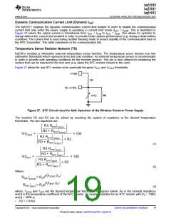
Where fS is 100 kHz +5/-10% and fD is 1 MHz ±10%. C1 must be chosen first prior to calculating C2.
The quality factor must be greater than 77 and can be determined by Equation 5:
2p × fD × LS
Q =
R
where R is the DC resistance of the receiver coil. All other constants are defined above.
Receiver Coil Load-Line Analysis
When choosing a receiver coil, it is recommend to analyze the transformer characteristics between the primary
coil and receiver coil via load-line analysis. This will capture two important conditions in the WPC system:
1. Operating point characteristics in the closed loop of the WPC system.
2. Instantaneous transient response prior to the convergence of the new operating point.
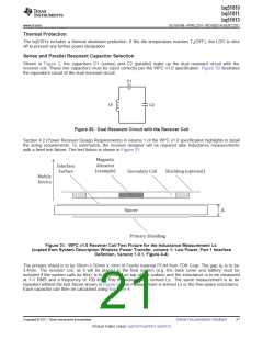
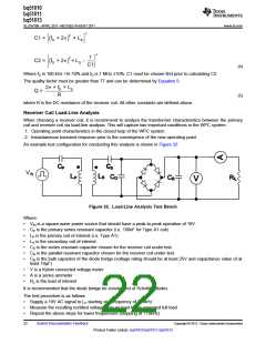
An example test configuration for conducting this analysis is shown in Figure 32:
CP
CS
VIN
LP
LS C
D
CB
RL
V
Figure 32. Load-Line Analysis Test Bench
Where:
•
•
•
•
•
•
•
VIN is a square-wave power source that should have a peak-to-peak operation of 19V.
CP is the primary series resonant capacitor (i.e. 100nF for Type A1 coil).
LP is the primary coil of interest (i.e. Type A1).
LS is the secondary coil of interest.
CS is the series resonant capacitor chosen for the receiver coil under test.
CD is the parallel resonant capacitor chosen for the receiver coil under test.
CB is the bulk capacitor of the diode bridge (voltage rating should be at least 25V and capacitance value of at
least 10µF)
•
•
•
V is a Kelvin connected voltage meter
A is a series ammeter
RL is the load of interest
It is recommended that the diode bridge be constructed of Schottky diodes.
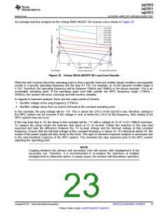
The test procedure is as follows
•
•
•
Supply a 19V AC signal to LP starting at a frequency of 210kHz
Measure the resulting rectified voltage from no load to the expected full load
Repeat the above steps for lower frequencies (stopping at 110kHz)
22
Submit Documentation Feedback
Copyright © 2011, Texas Instruments Incorporated
Product Folder Link(s): bq51010 bq51011 bq51013

 TI [ TEXAS INSTRUMENTS ]