bq51050B
bq51051B
www.ti.com
SLUSB42C –JULY 2012–REVISED FEBRUARY 2013
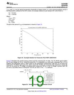
TCOLD and THOT are the desired temperature thresholds in degrees Kelvin. Ro is the nominal resistance and β is
the temperature coefficient of the NTC resistor. An example solution for part number ERT-JZEG103JA is:
R2 = 7.81 kΩ
R3 = 13.98 kΩ
Where,
TCOLD = 0°C
THOT = 0°C
β = 4500
Ro = 10 kΩ
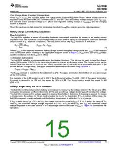
The plot of the percent VTSB vs temperature is shown in Figure 23:
Figure 23. Example Solution for Panasonic Part # ERT-JZEG103JA
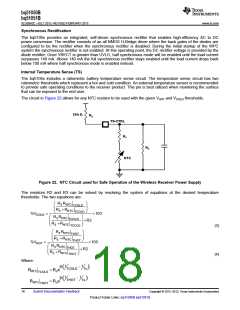
Figure 24 illustrates the periodic biasing scheme used for measuring the TS state. The TS_READ signal enables
the TS bias voltage for 25 ms. During this period the TS comparators are read (each comparator has a 10 ms
deglitch) and appropriate action is taken based on the temperature measurement. After this 25 ms period has
elapsed the TS_READ signal goes low, which causes the TS-Bias pin to become high impedance. During the
next 100 ms period the TS voltage is monitored and compared to 100 mV. If the TS voltage is greater than 100
mV then a secondary device is driving the TS/CTRL pin and a CTRL = ‘1’ is detected.
Figure 24. Timing Diagram for TS Detection Circuit
Copyright © 2012–2013, Texas Instruments Incorporated
Submit Documentation Feedback
19
Product Folder Links: bq51050B bq51051B

 TI [ TEXAS INSTRUMENTS ]