bq51050B
bq51051B
www.ti.com
SLUSB42C –JULY 2012–REVISED FEBRUARY 2013
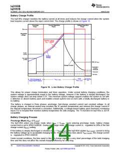
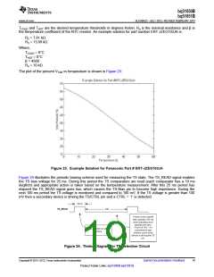
Fast Charge Mode /Constant Voltage Mode
Once VBAT > VLOWV, the bq5105x enters fast charge mode (Current Regulation Phase) where charge current is
regulated using the internal MOSFETs between RECT and BAT.Once the battery voltage charges up to VBAT-REG
,
the bq5105x enters constant voltage (CV) phase and regulates battery voltage to VBAT(REG) and the charging
current is reduced.
Once the input current falls below the termination threshold (ITERM),the charger goes into high impedance.
Battery Charge Current Setting Calculations
RILIM Calculations
The bq5105x includes a means of providing hardware overcurrent protection by means of an analog current
regulation loop. The hardware current limit provides an extra level of safety by clamping the maximum allowable
output current (e.g., a current compliance). The calculation for the total RILIM resistance is as follows:
300
R1 =
- RFOD
RILIM = R1 + RFOD
IBULK
(1)
Where IBULK is the expected maximum battery charge current during fast charge mode and IBULK is the hardware
over current limit. When referring to the application diagram shown in Figure 2, RILIM is the sum of RFOD(188Ω)
and the resistance from the ILIM pin to GND).
Termination Calculations
The bq5105X includes a programmable upper termination threshold. This pin can be used to send the charge
status 100% packet (CS100) to the transmitter in order to indicate a full charge status. The header for this packet
is 0x05. Note that this packet does not turn off the transmitter and is only used as an informative indication of the
mobile device’s charge status. The upper termination threshold is calculated using Equation 2:
RTERM = KTERM ´%IBULK
(2)
The KTERM constant is specified in the datasheet as 240. The upper termination threshold is set as a percentage
of the ILIM setting.
For example, if the ILIM resistor is set to 300 Ω the ILIM current will be 1A (300 ÷ 300). If the upper termination
threshold is desired to be 100 mA, this would be 10% of ILIM. The RTERM resistor would then equal 2.4 kΩ
(240 x 10).
Battery-Charger Safety and JEITA Guidelines
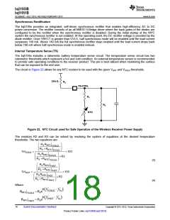
The bq5105x continuously monitors battery temperature by measuring the voltage between the TS pin and GND.
A negative temperature coefficient thermistor (NTC) and an external voltage divider typically develop this voltage.
The bq5105x compares this voltage against its internal thresholds to determine if charging is allowed. To initiate
a charge cycle, the voltage on TS pin must be within the VT1 to VT4 thresholds. If VTS is outside of this range, the
bq5105x suspends charge and waits until the battery temperature is within the VT1 to VT4 range.
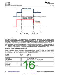
If VTS is within the range of VT1 and VT2, the charge current is reduced to IBULK/2. if VTS is within the range of VT2
and VT3, the maximum charge voltage regulation is 4.25V. if VTS is within VT3 and VT4, the maximum charge
voltage regulation is reduced back to 4.10V and charge current is reduced to IBULK/2. Figure 19 summarizes the
operation.
Copyright © 2012–2013, Texas Instruments Incorporated
Submit Documentation Feedback
15
Product Folder Links: bq51050B bq51051B

 TI [ TEXAS INSTRUMENTS ]