bq51050B
bq51051B
SLUSB42C –JULY 2012–REVISED FEBRUARY 2013
www.ti.com
Synchronous Rectification
The bq5105x provides an integrated, self-driven synchronous rectifier that enables high-efficiency AC to DC
power conversion. The rectifier consists of an all NMOS H-Bridge driver where the back gates of the diodes are
configured to be the rectifier when the synchronous rectifier is disabled. During the initial startup of the WPC
system the synchronous rectifier is not enabled. At this operating point, the DC rectifier voltage is provided by the
diode rectifier. Once VRECT is greater than UVLO, half synchronous mode will be enabled until the load current
surpasses 140 mA. Above 140 mA the full synchronous rectifier stays enabled until the load current drops back
below 100 mA where half synchronous mode is enabled instead.
Internal Temperature Sense (TS)
The bq5105x includes a ratiometric battery temperature sense circuit. The temperature sense circuit has two
ratiometric thresholds which represent a hot and cold condition. An external temperature sensor is recommended
to provide safe operating conditions to the receiver product. This pin is best utilized when monitoring the surface
that can be exposed to the end user.
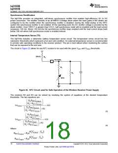
The circuit in Figure 22 allows for any NTC resistor to be used with the given VHOT and VCOLD thresholds.
20 kΩ
R2
TS-CTRL
R1
R3
NTC
Figure 22. NTC Circuit used for Safe Operation of the Wireless Receiver Power Supply
The resistors R2 and R3 can be solved by resolving the system of equations at the desired temperature
thresholds. The two equations are:
æ
ç
ç
è
ö
÷
÷
ø
R3 RNTC
TCOLD
R3 + RNTC
TCOLD
%VCOLD
=
´100
æ
ç
ç
è
ö
÷
÷
ø
R3 RNTC
TCOLD
+ R2
R3 + RNTC
TCOLD
(3)
(4)
æ
ç
ç
è
ö
÷
÷
ø
R3 RNTC
THOT
R3 + RNTC
THOT
%VHOT
=
´100
æ
ç
ç
è
ö
÷
÷
ø
R3 RNTC
THOT
+ R2
R3 + RNTC
THOT
Where:
RNTC
1
b
1
-
(
)
TCOLD
To
= Roe
TCOLD
1
1
b
-
(
)
THOT
To
RNTC
= Roe
THOT
18
Submit Documentation Feedback
Copyright © 2012–2013, Texas Instruments Incorporated
Product Folder Links: bq51050B bq51051B

 TI [ TEXAS INSTRUMENTS ]