bq51050B
bq51051B
www.ti.com
SLUSB42C –JULY 2012–REVISED FEBRUARY 2013
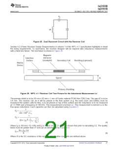
C1
Ls’
Figure 25. Dual Resonant Circuit with the Receiver Coil
Section 4.2 (Power Receiver Design Requirements) in volume 1 of the WPC v1.1 specification highlights in detail
the sizing requirements. To summarize, the receiver designer will be required take inductance measurements
with a fixed test fixture. The test fixture is shown in Figure 26:
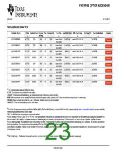
Figure 26. WPC v1.1 Receiver Coil Test Fixture for the Inductance Measurement Ls’
The primary shield is to be 50 mm x 50 mm x 1 mm of Ferrite material PC44 from TDK Corp. The gap dZ is to be
3.4 mm. The receiver coil, as it will be placed in the final system (e.g. the back cover and battery must be
included if the system calls for this), is to be placed on top of this surface and the inductance is to be measured
at 1-V RMS and a frequency of 100 kHz. This measurement is termed Ls’. This measurement is termed Ls or the
free-space inductance. Each capacitor can then be calculated using Equation 5:
1
C1 =
(2p´ ¦s)2 ´L's
1
C2 =
æ
ö
÷
ø
1
(2p´ ¦ )2 ´ L -
ç
D
s
C1
è
(5)
Where fS is 100 kHz +5/–10% and fD is 1 MHz ±10%. C1 must be chosen first prior to calculating C2. The quality
factor must be greater than 77 and can be determined by Equation 6:
2p´ ¦D ´Ls
Q =
R
(6)
Where R is the DC resistance of the receiver coil. All other constants are defined above.
Copyright © 2012–2013, Texas Instruments Incorporated
Submit Documentation Feedback
21
Product Folder Links: bq51050B bq51051B

 TI [ TEXAS INSTRUMENTS ]