bq51050B
bq51051B
www.ti.com
SLUSB42C –JULY 2012–REVISED FEBRUARY 2013
PRINCIPLE OF OPERATION
Power
bq5105x
Voltage/
Current
Conditioning
System
AC to DC
Drivers
Rectification
Communication
LI-Ion
Battery
Battery
Charger
Controller
V/I
Sense
Controller
bq500210
Transmitter
Receiver
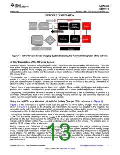
Figure 17. WPC Wireless Power Charging System Indicating the Functional Integration of the bq5105x
A Brief Description of the Wireless System
A wireless system consists of a charging pad (primary, transmitter) and the secondary-side equipment. There are
coils in the charging pad and in the secondary equipment which magnetically coupled to each other when the
equipment is placed on the charging pad. Power is transferred from the primary to the secondary by transformer
action between the coils. Control over the amount of power transferred is achieved by changing the frequency of
the primary drive.
The secondary can communicate with the primary by changing the load seen by the primary. This load variation
results in a change in the primary coil current, which is measured and interpreted by a processor in the charging
pad. The communication is digital - packets are transferred from the secondary to the primary. Differential Bi-
phase encoding is used for the packets. The bit rate is 2Kbits / second.
Various types of communication packets have been defined. These include identification and authentication
packets, error packets, control packets, power usage packets, end of power packet and efficiency packets.
The primary coil is powered off most of the time. It wakes up occasionally to see if a secondary is present. If a
secondary authenticates itself to the primary, the primary remains powered up. The secondary maintains full
control over the power transfer using communication packets.
Using the bq5105x as a Wireless Li-Ion/Li-Pol Battery Charger (With reference to Figure 2)
Figure 2 is the schematic of a system which uses the bq5105x as direct battery charger. When the system
shown in Figure 2 is placed on the charging pad (transmitter), the receiver coil couples to the magnetic flux
generated by the coil in the charging pad which consequently induces a voltage in the receiver coil. The internal
synchronous rectifier feeds this voltage to the RECT pin which has the filter capacitor C3.
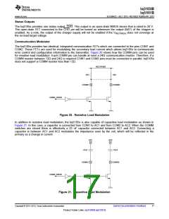
The bq5105x identifies and authenticates itself to the primary using the COM pins by switching on and off the
COM FETs and hence switching in and out CCOMM. If the authentication is successful, the transmitter will remain
powered on. The bq5105x measures the voltage at the RECT pin, calculates the difference between the actual
voltage and the desired voltage VRECT-REG and sends back error packets to the primary. This process goes on
until the RECT voltage settles at VRECT-REG
.
During power-up, the LDO is held off until the VRECT-REG threshold converges. The voltage control loop ensures
that the output (BAT) voltage is maintained at VBAT-REG to power the system depends on the battery charge
mode. The bq5105x continues to monitor the VRECT and VBAT and maintains sending error packets to the primary
every 250ms. The bq5105x regulates the VRECT voltage very close to battery voltage, this voltage tracking
process minimizes the voltage difference across the internal LDO and maximize the charging efficiency. If a large
transient occurs, the feedback to the primary speeds up to every 32ms in order to converge on an operating
point in less time.
Copyright © 2012–2013, Texas Instruments Incorporated
Submit Documentation Feedback
13
Product Folder Links: bq51050B bq51051B

 TI [ TEXAS INSTRUMENTS ]