bq3285
Periodic Interrupt
Update Cycle Interrupt
The mux output used to drive the SQW output also
drives the interrupt-generation circuitry. If the periodic
interrupt event is enabled by writing a 1 to the periodic
interrupt enable bit (PIE) in register C, an interrupt re-
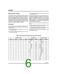
quest is generated once every 122µs to 500ms. The pe-
riod between interrupts is selected by the same bits in
register A that select the square wave frequency (see Ta-
ble 3).
The update cycle ended flag bit (UF) in register C is set
to a 1 at the end of an update cycle. If the update inter-
rupt enable bit (UIE) of register B is 1, and the update
transfer inhibit bit (UTI) in register B is 0, then an in-
terrupt request is generated at the end of each update
cycle.
Accessing RTC bytes
Alarm Interrupt
Time and calendar bytes read during an update cycle
may be in error. Three methods to access the time and
calendar bytes without ambiguity are:
During each update cycle, the RTC compares the hours,
minutes, and seconds bytes with the three corresponding
alarm bytes. If a match of all bytes is found, the alarm
interrupt event flag bit, AF in register C, is set to 1. If
the alarm event is enabled, an interrupt request is gen-
erated.
n
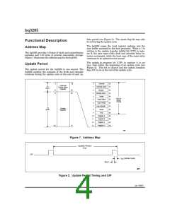
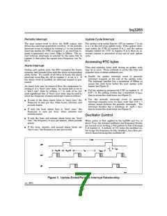
Enable the update interrupt event to generate
interrupt requests at the end of the update cycle.
The interrupt handler has a maximum of 999ms to
access the clock bytes before the next update cycle
begins (see Figure 3).
An alarm byte may be removed from the comparison by
setting it to a “don’t care” state. An alarm byte is set to
a “don’t care” state by writing a 1 to each of its two
most-significant bits. A “don’t care” state may be used to
select the frequency of alarm interrupt events as follows:
n
n
Poll the update-in-progress bit (UIP) in register A. If
UIP = 0, the polling routine has a minimum of tBUC
time to access the clock bytes (see Figure 3).
Use the periodic interrupt event to generate
interrupt requests every tPI time, such that UIP = 1
always occurs between the periodic interrupts. The
interrupt handler has a minimum of tPI/2 + tBUC
time to access the clock bytes (see Figure 3).
n
n
n
n
If none of the three alarm bytes is “don’t care,” the
frequency is once per day, when hours, minutes, and
seconds match.
If only the hour alarm byte is “don’t care,” the
frequency is once per hour, when minutes and
seconds match.
Oscillator Control
If only the hour and minute alarm bytes are “don’t
care,” the frequency is once per minute, when seconds
match.
When power is first applied to the bq3285 and VCC is
above VPFD, the internal oscillator and frequency divider
are turned on by writing a 010 pattern to bits 4 through
6 of register A. A pattern of 11X turns the oscillator on,
but keeps the frequency divider disabled. Any other pat-
tern to these bits keeps the oscillator off.
If the hour, minute, and second alarm bytes are
“don’t care,” the frequency is once per second.
Figure 3. Update-Ended/Periodic Interrupt Relationship
Jan. 1999 E
7

 TI [ TEXAS INSTRUMENTS ]